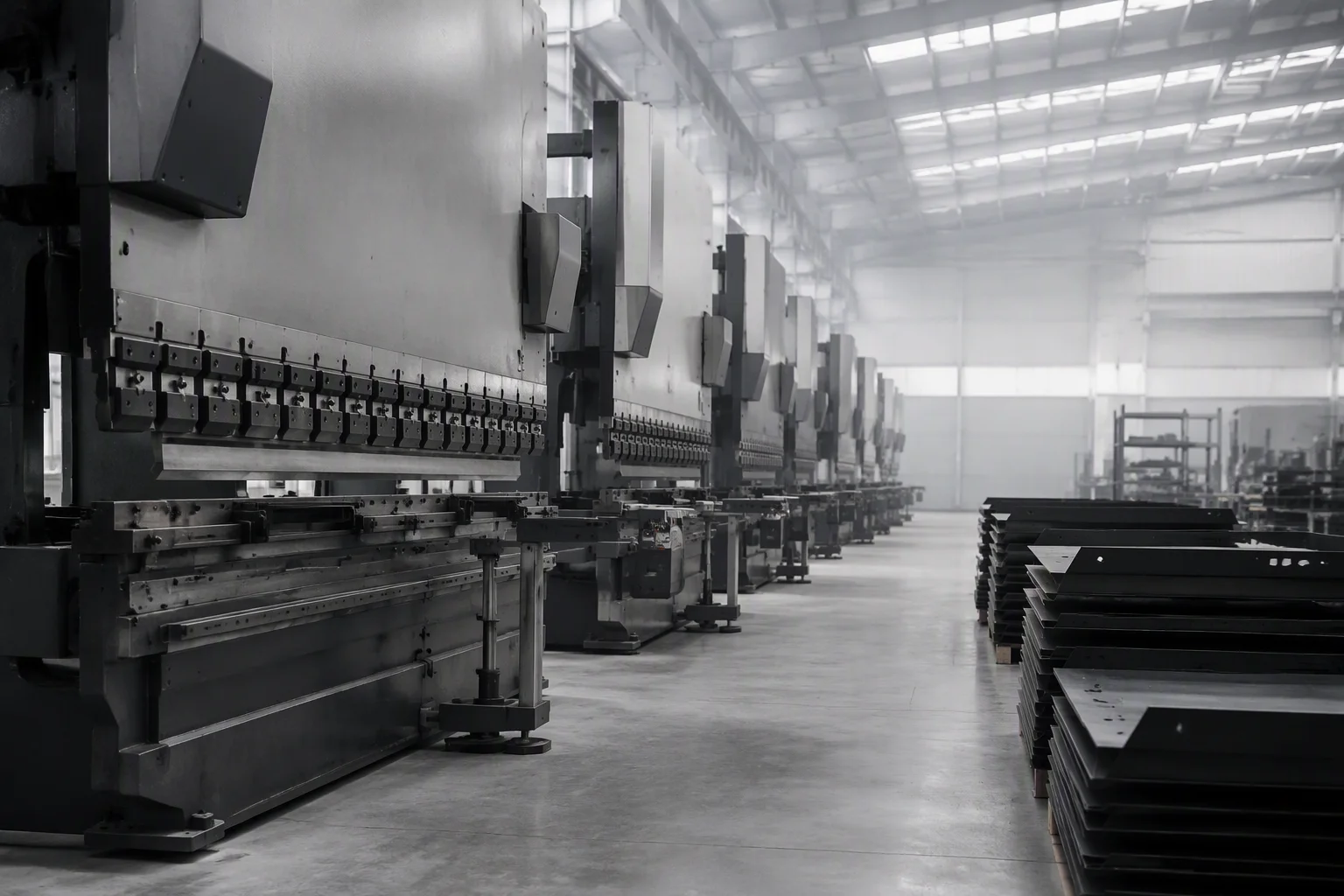
Every process your rack needs is behind one door
Coil steel enters at one end and a crated rack leaves at the other, passing through six processes we run ourselves: laser cutting, CNC punching, bending, welding, powder coating and assembly. Nothing critical is subcontracted, so lead time answers to one schedule — 30 days standard FOB, 15 days for a sample — and tolerance answers to one system: ±0.1 mm from laser through assembly.
The window is 0.8–3.0 mm sheet in SPCC, SGCC, SUS304 and AL5052, with rack structures built at 1.2–2.0 mm and a C4-class coating system validated to 480 hours of neutral salt spray.
Six steps from coil to crate
Each step hands the next one a measurable state, not a promise: cut sheets with broken burrs, formed parts within jig tolerance, weldments ground to the finish class, coated panels with grounding points masked bare. Where your input changes the outcome, it is listed with the step.
Laser
Fiber laser nests are programmed before the first cut, which sets both scrap rate and hole position — ±0.05 mm positioning repeatability across the 0.8–3.0 mm window. Rail, shelf and power-shelf positions land on the sheet, not in later drilling. Your input: DXF or DWG with 1:1 flat patterns; we return DFM notes within 48 hours.
Punch
The turret punch forms louver vents, knockouts, countersinks and cable-guide slots in one hit — faster than laser for repeatable hole fields, at ±0.1 mm accuracy. The tooling library already covers the vent patterns used across server racks and containment panels. Your input: hole and vent callouts with tolerances marked on the drawing.
Bend
CNC press brakes hold ±0.1 mm on repeat bends, and the signature five-bend 2.0 mm upright profile is formed in a single setup so column spacing never drifts across a 24-rack order. Gauging jigs keep the batch consistent, not just the first sheet. Your input: approval of the bend sequence proposed on the DFM sheet.
Weld
TIG joins SUS304, MIG builds frames, and spot welding closes panel assemblies; fixture-cooled sequences keep thin-gauge parts flat. Cosmetic welds are ground to the finish class the drawing calls out, and every ground-bond point stays weld-verified before coating. Your input: weld-on and weld-off marks plus the cosmetic-face list.
Coat
Four-stage pretreatment — degrease, pickle, phosphate, rinse — feeds an electrostatic powder line at 80–100 µm, rated C4 and batch-validated to 480 h neutral salt spray (ISO 9227) with ISO 2409 adhesion at class 0. Masking keeps threads and grounding points bare. Your input: RAL code, gloss level and masking points.
Assemble
Hardware insertion, sub-assembly and logged-torque closing run against the serial number that will ship inside the crate with the test log. Ground continuity is measured frame-to-frame at ≤0.1 Ω before anything is packed. Your input: fastener specification and preferred export packing — plywood crate or CKD flat-pack.
Three bays that decide the tolerances
Tolerances are not inspected into a rack at the end — they are created where the steel is cut, bent and coated. These are the three bays a factory tour spends the most time in.
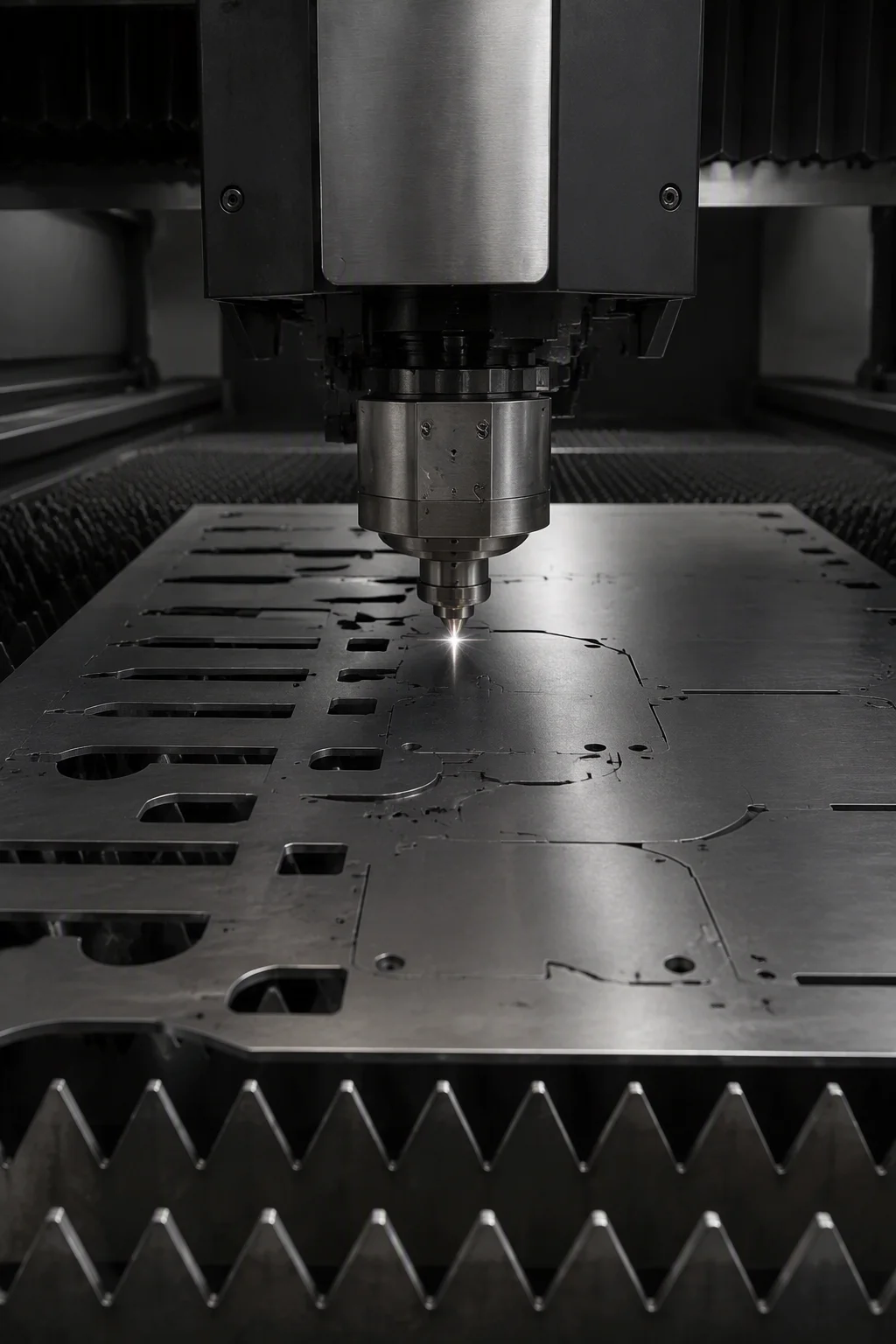
Cut once, position forever
Nesting software programs every hole and slot before the sheet is cut, so rail and shelf positions arrive at assembly as-cut at ±0.05 mm — the reason a 24-rack row lines up without shimming.
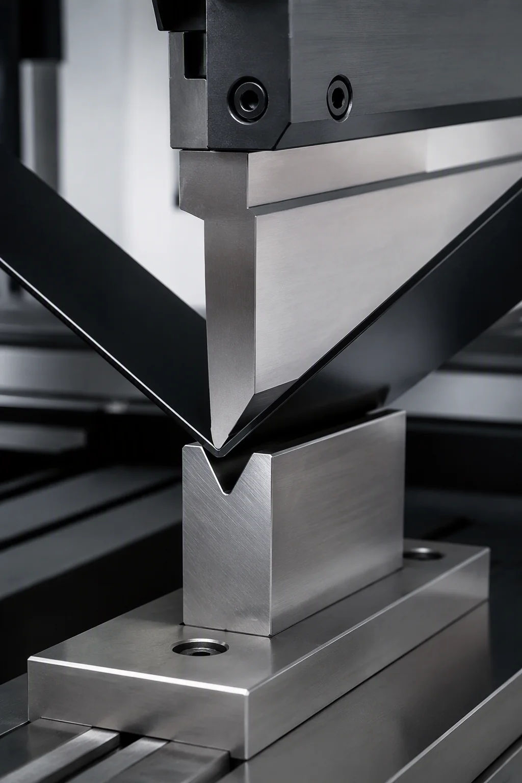
The five-bend column
Uprights get their stiffness from geometry, not gauge: five bends in one setup on 2.0 mm SPCC, held to ±0.1 mm by batch jigs so EIA hole patterns stay true down the whole row.
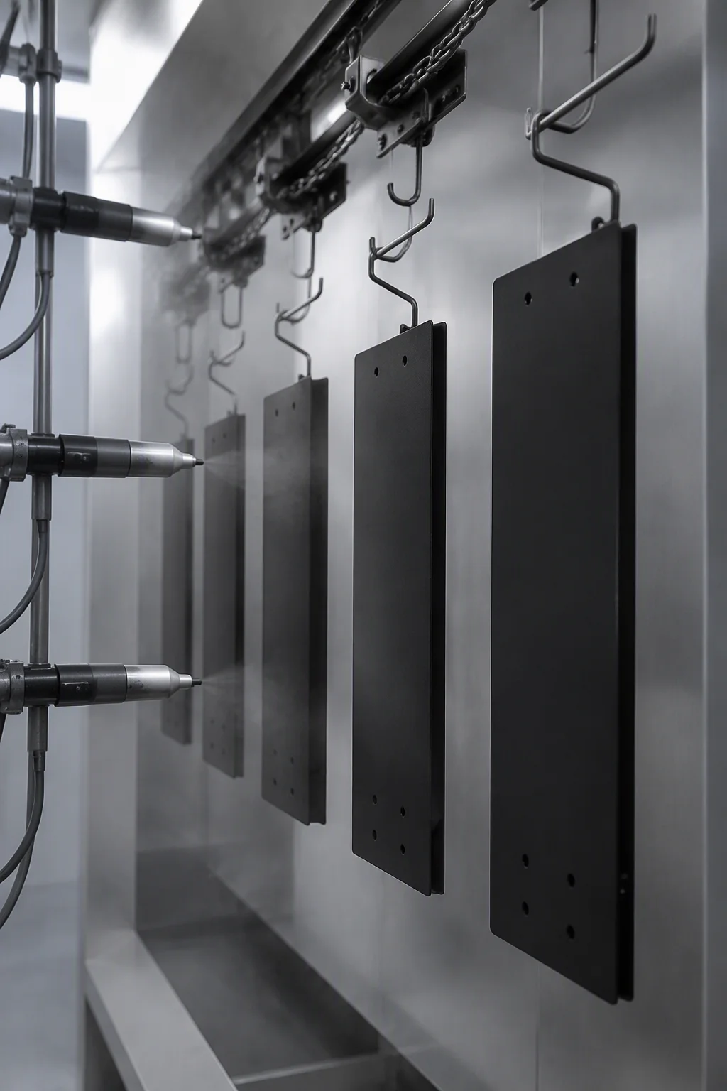
Coating as corrosion engineering
The 80–100 µm C4 powder system is chosen for coastal and industrial sites, proven to 480 h of salt spray per batch — a finish warranty the 3-year coverage stands behind.
What the line holds, process by process
Published as process capability rather than a machine list: the numbers below are what the bays are routinely held to on rack work, and they are the same values quoted on OEM drawings. Nameplate ratings are shared during factory visits and quotation, matched to the parts in your order.
| Process | Capability & control |
|---|---|
| Materials | SPCC · SGCC · SUS304 · AL5052, mill certificates retained per batch |
| Sheet thickness window | 0.8–3.0 mm · rack structures 1.2–2.0 mm · uprights 2.0 mm |
| Laser cutting line | fiber source, full 0.8–3.0 mm window · ±0.05 mm positioning repeatability |
| CNC punching | louver / knockout / countersink tooling library · ±0.1 mm punched, ±0.05 mm laser-cut holes |
| Bending line | CNC press brakes · ±0.1 mm repeat bends · five-bend 2.0 mm uprights in one setup |
| Welding | TIG (SUS304) · MIG (frames) · spot (panels) · fixture-cooled distortion control |
| Pretreatment | 4-stage: degrease → pickle → phosphate → rinse |
| Powder coating line | electrostatic, 80–100 µm nominal · C4 class (ISO 12944-2) · threads and grounds masked bare |
| Coating validation | ISO 9227 neutral salt spray 480 h per batch · ISO 2409 adhesion class 0 |
| Measurement | granite CMM first article against ballooned drawing · ±0.1 mm fabrication tolerance |
| Assembly & torque | calibrated tooling, logged torque · ground continuity ≤0.1 Ω frame-to-frame |
| Traceability | serial-matched QC log in every crate · batch-retained material certificates |
See the six bays run before your order enters them
Factory tours by appointment · 0.8–3.0 mm window · 30-day FOB, MOQ 5