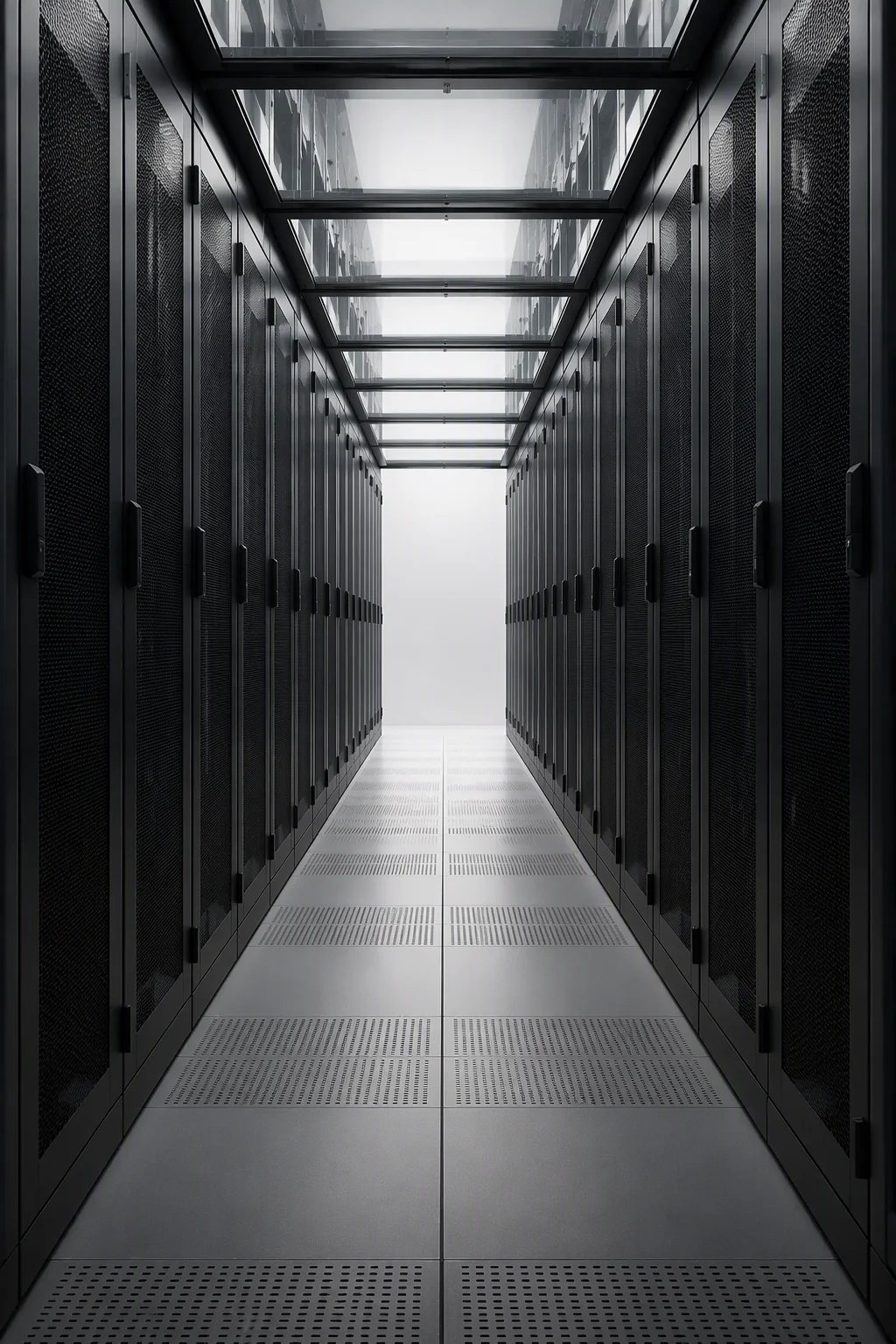
Size it, contain it, integrate it
Most rack projects go wrong in one of three places: the cabinet was sized to the marketing sheet instead of the heat, the aisle was closed in the wrong order, or the busway and coolant routes were never reserved until the day they were needed. These three guides follow that order on purpose — chapters first as a field manual, then the full written guides below. Everything in them is stated in numbers you can check against your own hall.
Read the Three Guides Ask an Engineer
8→40→132 kW sizing path · PUE 1.84→1.65 measured case · 400 kW/rack-position busway ceiling
Three chapters that decide the project
Printed version of the decision sequence our engineers walk through on every quotation call. If your project already passes these three chapters, the quotation is a formality — send it over.
Size it right — count the heat, then choose the cabinet
- Path by kilowatts: up to 8 kW runs a standard air-cooled frame; 8–40 kW is GPU air build territory, at the practical front-to-back airflow limit; above 40 kW the liquid path takes over, from 40 to 132 kW per cabinet.
- Then check weight: total IT load plus rack net weight must sit under the static rating — 1,500 kg standard, 1,600 kg high-density, each proven at a 4× factor with a 72-hour creep recheck.
- Then check the floor: as a reference, rack install manuals commonly expect slab capacity near 490 kg/m² (100 PSF) under concentrated rows — verify yours before ordering.
- Oversizing one axis is cheap at order time and expensive at install time; the sizing guide carries the full decision tree.
Contain it — close the aisle your room can hold
- Cold-aisle containment is the retrofit default: the room becomes the return plenum and existing CRAC/CRAH units keep working — a measured mild-climate case moved PUE from 1.84 uncontained to 1.65 contained.
- Hot-aisle can go further, but only in rooms with a ceiling-level return path; it has prerequisites, and the guide lists them before the savings numbers.
- Fire first, always: drop-away roof panels release below 72 °C and doors open on the fire alarm in under 3 seconds, so containment never blocks suppression.
- Retrofit priority: blanking panels and brush sealing first — around 30 seconds per U, tool-free — doors and roof second, full boundary last.
Integrate it — reserve for power, coolant and weight on day one
- Busway: our columns carry a machined tap-off track with a 400 kW per rack-position design ceiling — plan feed at the 800 A class now, not the 400 A habit of older halls.
- Liquid: manifolds and UQD quick disconnects mount above both doors at 25–80 L/min on PG25, factory pressure-held at 1.5× working pressure for 24 hours.
- Structure: bayning and anchor points come on the GA drawing, so rows brace as one frame instead of 24 single cabinets.
- Sequence decides cost: rows set, then busway, then manifolds, then containment doors and roof — closing the aisle before pipe runs means reopening it.
Three guides, read online in about ten minutes each
No download, no gated form — the full guides live on the engineering blog, next to the numbers they cite. Each one ends with a checklist you can run against your own room before you request a quotation.
From 8 kW to 132 kW — Sizing AI Racks
- The kW decision tree: air, GPU air, liquid
- Where air cooling ends, and why 40 kW is the line
- Weight and floor checks with real ratings
Cold-Aisle vs Hot-Aisle Containment
- Which closure fits which room, with the measured PUE case
- What hot-aisle needs from your ceiling before it pays
- Fire interlock: drop-away panels and FA door release
Busbar & Liquid-Cooling Rack Integration
- Busbar planning at the 800 A class, 400 kW per position
- Manifold routing, UQD positions and factory pressure holds
- Installation sequence that avoids reopening the aisle
Where projects stall — and the way through
Three questions that stop sizing exercises mid-way, answered with the same numbers the guides use. The full trade and shipping list of eighteen lives on the FAQ page.
Blanking panels and brush sealing go in at any time — they need nothing but an empty U and half a minute each. Doors and roof panels are installed with the row: racks set and bayed first, then the boundary closed around them, so panel cuts match real rack positions instead of drawing ones. Containment is the last thing closed and the first thing the fire system is checked against.
Work in two steps. First the rack: total IT load plus the frame's own weight must sit under the static rating, which our frames prove at a 4× safety factor. Then the slab: concentrated rows load a footprint, so compare against your floor's rated capacity — a common reference point in rack install manuals is about 490 kg/m² (100 PSF). If you send the floor drawing and row layout, the quotation includes the anchor and baying positions, and flagged rows can be re-planned before anything is ordered.
Our frames are built for it — busbar-ready column slots and liquid manifolds with UQD positions are factory-fitted on the relevant lines, so integration is a planning exercise, not a retrofit. Third-party racks are case by case: adapter mounting for overhead busway is often workable, while internal manifolds really want the liquid-cooling ready build because the pressure hold is done at the factory. The integration guide walks the decision, and the 48-hour engineering reply will tell you honestly which side your row falls on.
Run the guides, then send us the hard part
Layout review within 48 hours · 8→132 kW sizing path · MOQ 5, sample 1