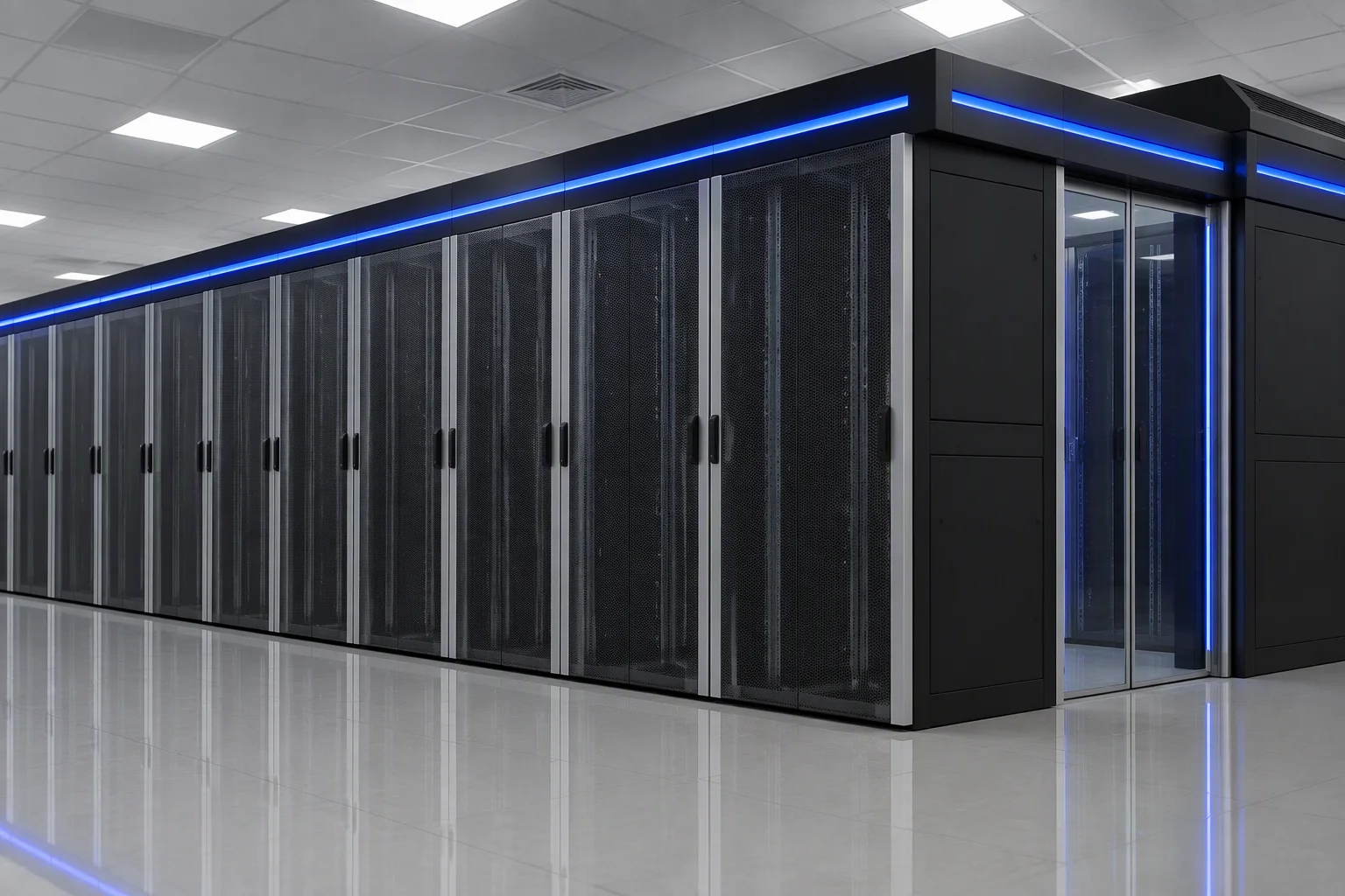
Design guide · 04
Power & Grounding
Two things decide whether a rack row is buildable: where the power comes in, and how the bonding path is proven. This guide walks that chain and shows the measured values from the third-party reports on our own cabinets.
Our scope on this page: the distribution cabinet, the rack-level feed provision, and the bonding path. Utility intake, UPS and generation are outside it, and the diagram says so.
Layers
From the utility intake to the rack: the interface to settle on each layer.
| Layer | What it is | Interface to define before order | In our scope |
|---|---|---|---|
| 1 · Utility intake | Incoming supply from the site transformer | Capacity, voltage, single or dual feed | No: facility |
| 2 · LV switchboard | Main low-voltage distribution for the hall | Fault level, breaker type, metering point | No: facility |
| 3 · UPS | Ride-through for the IT load | Whole hall or one row; autonomy target | No: partner brand |
| 4 · Precision column-header cabinet | Row-level distribution cabinet, fed from the UPS | Feed arrangement, outgoing ways and ratings, metering provisions | Yes: we build the cabinet body |
| 5 · Row-level cable route | How the feed reaches the rack positions | Route (overhead or underfloor), tray or ladder, data segregation | Provision only: you design the route |
| 6 · Busway provision | Space and mounting provision for an intelligent busway, if used | Busway-fed or cable-fed; vendor and its mounting standard | Provision only: third-party busway |
| 7 · Rack-level feed | The final run into each cabinet | Top or bottom entry; PDU or terminal block | Yes: provision in the cabinet |
| 8 · PDU position | Where a vertical PDU mounts inside the cabinet | PDU height, mounting standard, metered or switched | Provision only: position and fixing points |
| 9 · Vertical cable management | Vertical duct carrying feed and data cabling inside the cabinet | PDU fixing inside the duct; power and data separation | Yes: mounting holes for common PDU models |
| 10 · Bonding of the cabinet | Puts frame, front door and rear door at the same potential | Bonding conductor size; dedicated strap or through the hinge | Yes: multi-point, front door, rear door, frame |
| 11 · Earth bar and the run to the room earth | Cabinet earthing lead-out and its connection to the room grid | Earthing conductor size and route; room arrangement | Yes for the earthing point; room run is yours |
| 12 · Verification | How the bonding is proven and recorded | Whether you require a measured value at handover | Yes: measured values in the reports below |
Provision
What we leave, and what you fit.
ProvisionProvision for an intelligent busway and for PDUs is built into the cabinet and the rack: position, fixing points and cable route.
Third partyThe busway itself and the PDUs are third-party equipment: not supplied by us, not integrated by us, not shipped with the cabinet.
IntegrationWe support integration of third-party busway and PDUs: our provision follows a documented fixing standard, so your vendor's equipment lands on it.
AskIf your design uses a busway, send the vendor's mounting drawing with your enquiry; we will confirm the provision against it.
Bonding
How the bonded parts meet at the earthing point.
- 01Frame bonding first: establish the earthing point before anything is fitted to the frame.
- 02Bond every removable panel that carries equipment or closes the EMC envelope: front and rear doors.
- 03Bond through a conducting surface: masked, plated or toothed. Powder coat is an insulator; a bonding point on top of it is a drawing error.
- 04Measure at the earthing lead-out, not at the door. Record the value; the reports on this page do exactly that.
Measurement
What the reports measured, and where to find the line.
Both are third-party inspection reports, and both are on this page: the requirement and measured columns can be read against each other without leaving it.
Drawing review
Questions to ask any supplier, including us.
- 01Ask which standard the cabinet was type-tested against, and for the report number.
- 02Ask for the measured DC bonding resistance at the earthing lead-out, not a target.
- 03Ask whether both doors are bonded, or only the frame.
- 04Ask how the bonding point gets through the coating: masked, plated or toothed.
- 05Ask where the earthing point is, and how the room conductor lands on it.
- 06Ask for the cabinet outline as a drawing, not a photograph, before fixing the row pitch.
- 07Ask for the duct width and whether your PDU will fix inside it.
- 08Ask whether power and data are separated along the top route.
- 09Ask explicitly: is the busway supplied, or is there a provision? Get it in writing.
- 10Ask for the fixing standard of the busway provision, and check your vendor's drawing against it.
- 11Ask for the single-line diagram of the cabinet you are quoted.
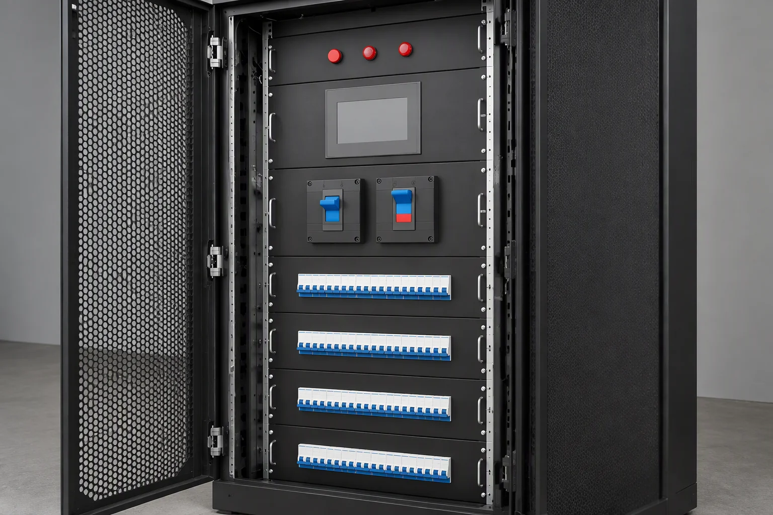
A single-line diagram and a row pitch is enough for us to come back with the cabinet arrangement and the rack-level provision.
If something in your diagram is outside what we build, we will say which part it is.
Send us your single-line diagram