Capability · liquid cooling
Cold-plate liquid cooling, configured to order.
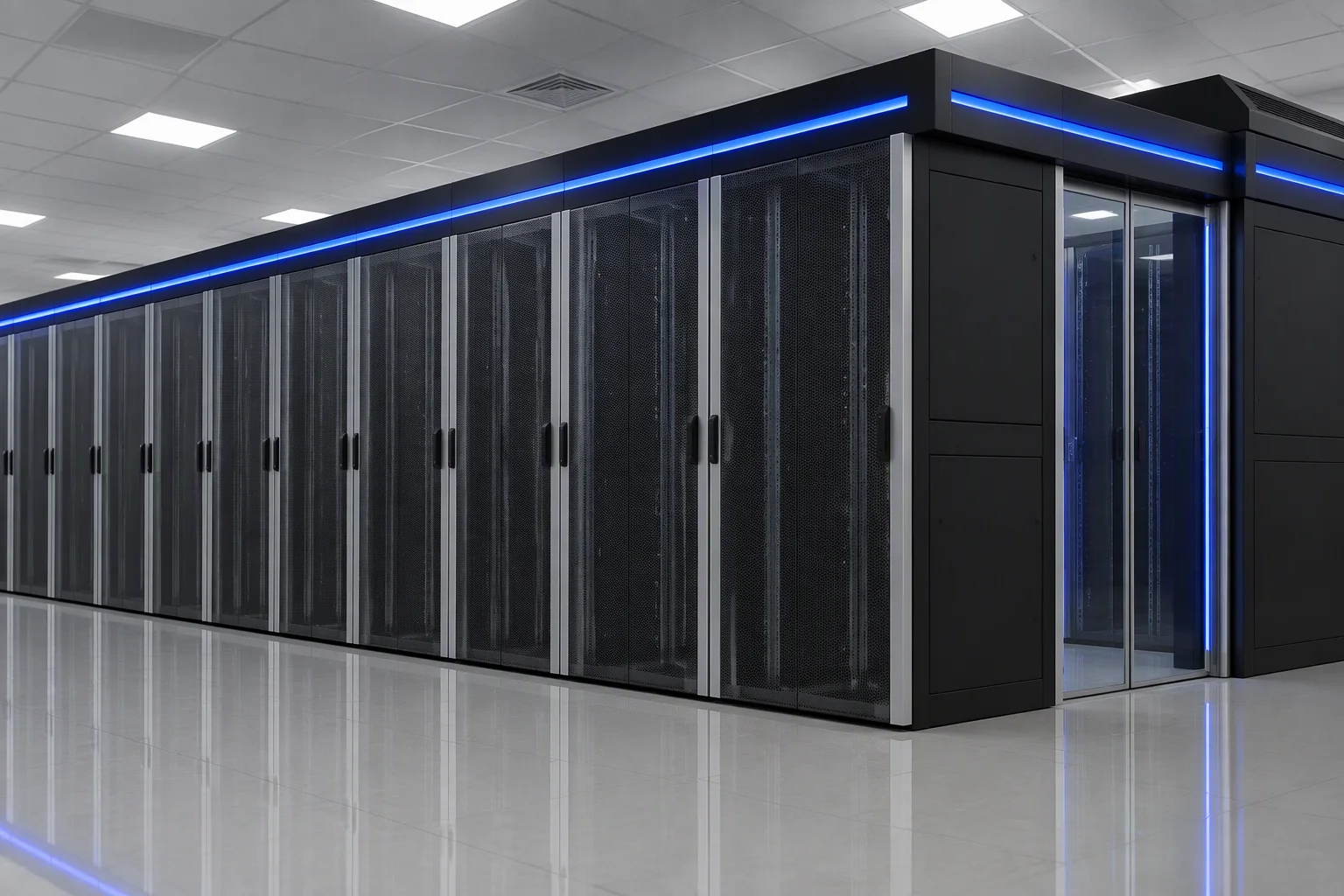
Cold plate is the route we build. Immersion is an optional route we assess per project. The parts below are named on the drawing, and the heat-rejection figure is set at selection with you — not printed here as a number that would not hold in your room.
- Cold plate
- CDU N+1
- Leak detection
- PUE ≤ 1.1 target
Two routes
Which route, and why that one
Cold plate and immersion solve different problems. We will tell you which one fits the room you have, and we will say so before you commit to a row design.
Cold plate — the route we build
- Sits on the processors, so the rest of the rack stays air-cooled and serviceable.
- Retrofits cabinet by cabinet, inside an existing air-cooled room.
- Keeps standard servers and standard rails — no immersion-rated hardware.
Immersion — optional route
- Assessed per project against the hardware list, not offered as a standard package.
- Changes the service routine, the fluid handling and the floor loading.
- We quote it only after the site conditions are on the table.
The four parts
CDU, cold plate, quick connector, leak detection
Four parts carry the loop. Each one is named on the drawing, and each one has a question attached that only your layout can answer.
- CDU
- The heat exchanger and pump unit, N+1 redundant. Selection confirms the number and the position of the units.
- Cold plate
- One per processor, matched to the server platform going into the rack. Selection confirms the plate set against your hardware list.
- Quick connector
- Keyed and tool-free, so a node can be pulled without draining the loop. Selection confirms the type and size against the plate set.
- Leak detection
- Sensors at the cabinet base, at the connection points and around the CDU. Selection confirms the zone count and the alarm mapping.
Specification
What is fixed, and what is set at selection
One column is settled by the platform. The other column is settled with you, before the drawing is released. The row that matters most is the second one.
| Parameter | Fixed | Configured at selection |
|---|---|---|
| Cooling method | Cold plate (direct to chip) | Immersion is an optional route, assessed per project |
| Heat-rejection capacity | — | Configured at selection — no catalogue figure applies to every room |
| CDU configuration | N+1 redundant | Number and position of units |
| CDU position | — | In-row or end-of-row, set with the row layout |
| Cold plates | — | Matched to the server platforms going into the rack |
| Quick connectors | Keyed and tool-free | Type and size, confirmed against the plate set |
| Leak detection | Sensors at the cabinet base, at connection points, and around the CDU | Zone count and alarm mapping |
| Loop routing | — | Single run, or ring / twin run, set by the row design |
| PUE target | ≤ 1.1 on a contained, liquid-cooled row | — |
| Rack height | 42U = 2000 mm · 47U = 2200 mm | Other heights built to order |
| Rack width × depth | 600×1200 mm · 800×1200 mm | 600×1000 mm · 600×1100 mm |
| Materials | Baosteel / Ansteel SPCC cold-rolled steel; 2.0 mm uprights, 1.2 mm doors | — |
| Static load | 1,000 kg standard | 1,500 kg on reinforced-frame models |
| Door mesh | Front ≥75%, rear ≥60% | — |
| Surface finish | Degrease → phosphating → electrostatic powder coating | — |
| Grounding | Front door, rear door and frame — multiple points | — |
| Shipping documents | ISO 9001 / 14001 / 45001 certificates and third-party test reports | — |
Leak detection and operation
If it leaks, what happens
Leak detection is not a feature list. It is a zone map, an alarm, and an action that already exists before anything goes wrong.
- Detection
- Sensors sit at the cabinet base, at the connection points and around the CDU — the three places a loop can weep.
- Alarm
- Any sensor in a zone raises an alarm and interlocks with the power feed to that row. The alarm names the row, not the building.
- Loop layout
- Main runs are single or ring / twin, set by the row design. It is a drawing decision, taken with the containment layout.
- CDU N+1
- One unit can be taken out for service without stopping the loop, which is what the redundancy is for.
Same cabinet
The loop changes. The cabinet does not.
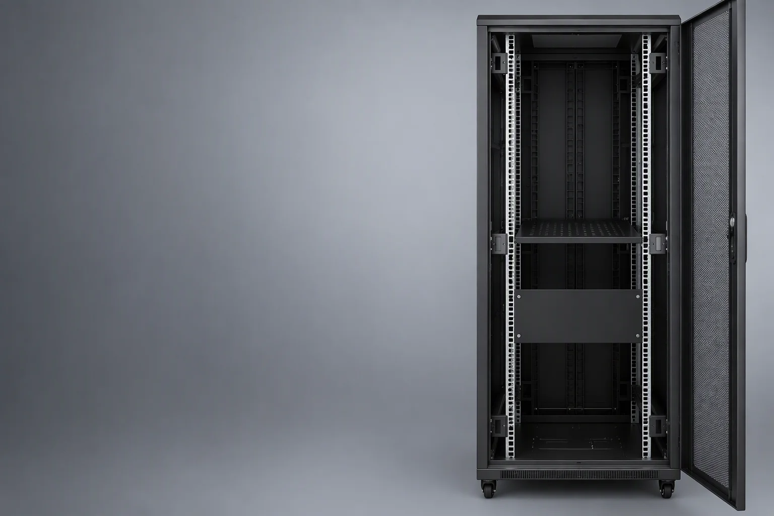
A cold-plate row is still built on the rack body the rest of the range uses — same steel, same uprights, same doors, same finish line.
That matters at handover: the row, the containment and the cabinets around it are one product family, not three suppliers meeting on site.
- Rack height
- 42U2000 mm47U2200 mm
- Steel
- Baosteel / Ansteel SPCC cold-rolled, 2.0 mm uprights, 1.2 mm doors
- Door mesh
- Front ≥75% · rear ≥60%
- Static load
- 1,000 kg standard · 1,500 kg on reinforced-frame models
42U cabinet, front door open — the same rack body used across the range.
Documents
What we can put in your hands today
Scope note, stated plainly: these certificates and third-party reports cover the rack and containment lines. There is no third-party liquid-cooling report in this set, and nothing here should be read as one.
3 granted utility model patents and 1 software copyright are held on the rack and containment lines. The reports above travel with the order; ask for any of them as a PDF with your enquiry.
Selection
Four steps, and the last one is a document
-
01
Rack layout and row design
Cabinet count, row length, containment type and where a CDU can physically stand.
-
02
Server platform and heat-load target
What goes in the racks and what the row has to reject. This is the input that sets the plate set.
-
03
Room conditions
Power feed, fire response and floor — the three site facts that decide how the loop is routed.
-
04
Loop scheme and component list
You get the scheme and the parts list as documents, and the component list becomes the order annex.
No step in this list carries a time figure, because none of them is a delivery promise. The delivery date is set once the loop scheme is signed.
Next step
Send the layout, not a question about capacity
Rack layout, server platform and heat-load target — we answer with a loop scheme and the component list.
Every request is either accepted or explicitly refused — never silently dropped.