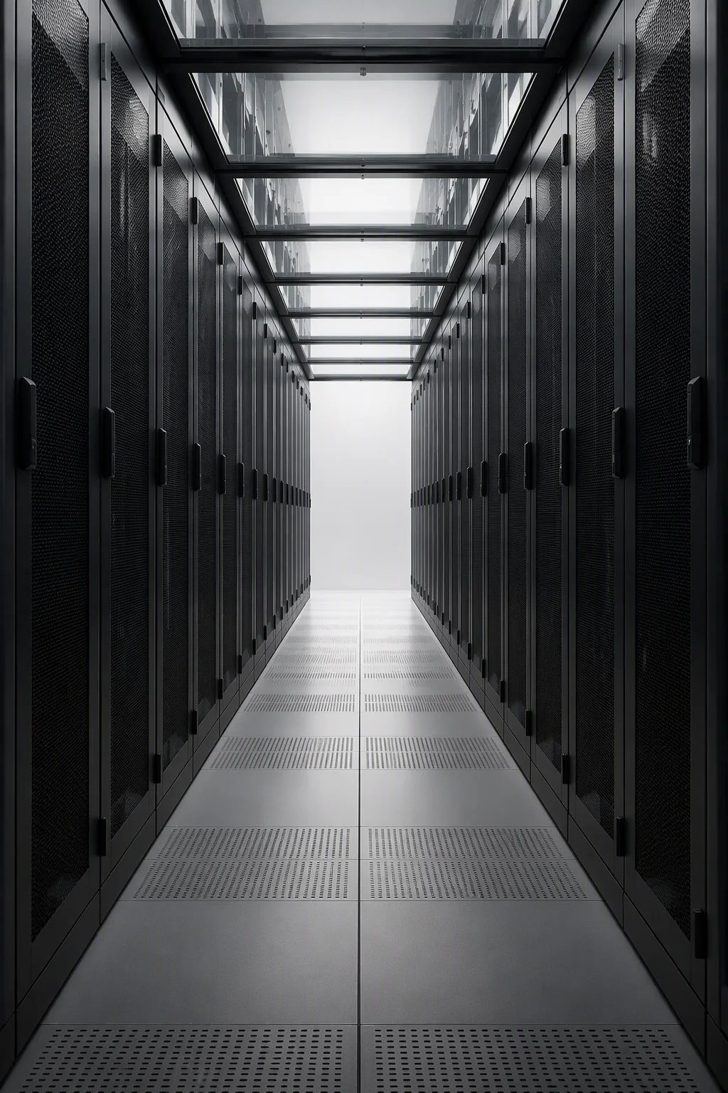
The design rule that governs everything else on the wet side is simple: no coolant inside the service zone unless it is being pumped. Above roughly 40 kW per cabinet, air stops being a practical coolant, and a direct-to-chip loop captures on the order of 98% of IT heat in DLC-2-class systems. That efficiency is only realisable if the loop is assembled to a drawing, tested before dispatch and built so that ordinary maintenance does not put water over live equipment.
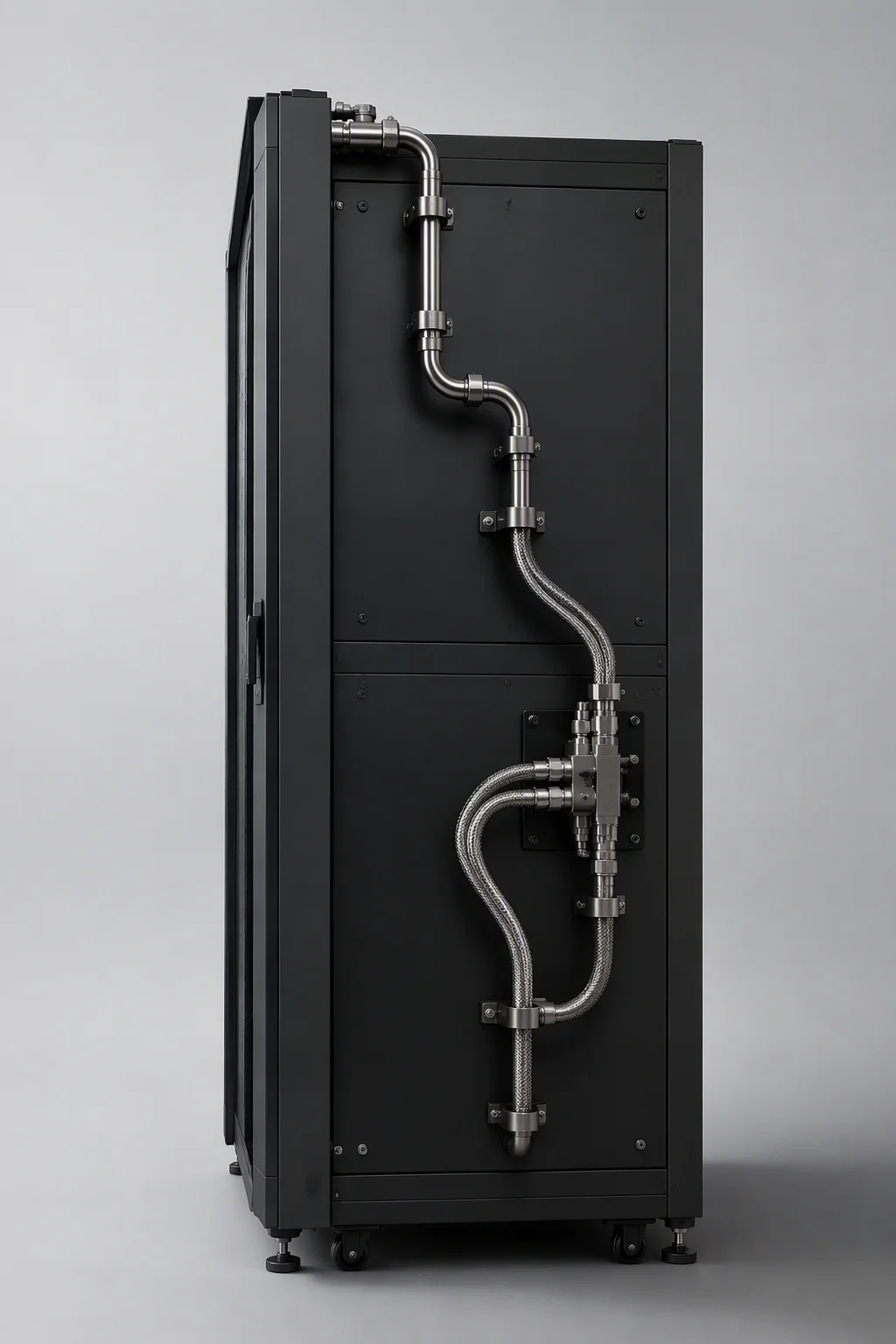
Manifold routing: above both door lines, not around them
Rack manifolds run above the front and rear door lines. The reason is space accounting rather than aesthetics:
- U positions stay sellable. A manifold inside the 42U–52U envelope consumes rack units that the customer paid for. Routing it over the door frame keeps every U available for compute.
- Both door lines, not one. Supply and return headers over opposite door lines mean a hose never crosses the service aisle or a hot aisle walkway, and a technician opening a door never disturbs a pressurised line.
- Branch positions are drilled to the approved layout drawing, and each assembly is numbered against the drawing revision it was built to — so the crew on site knows which revision is inside which crate.
- Bores are sized for the row, not the cabinet. DN50 rack manifolds and DN100–DN150 row headers are the design-alignment figures this family is built around.
Flow on this envelope is 25–80 L/min per rack, balanced per branch, on PG25 — a 25% propylene glycol and water mix. Balance is a manifold property: equal branch resistance is what keeps the last cabinet on a row from starving while the first one floods.
UQD placement: fixed coordinates or nothing
Quick disconnects are the handshake between the rack and the cooling distribution unit, and handshakes fail when one side moves. UQD pairs sit at fixed, repeatable coordinates so that any CDU in the in-rack class up to 250 kW can dock without re-engineering the rack — and so that a replacement CDU from a different supplier still lines up. The bodies are drip-less, capped and tagged at dispatch, and the interface follows published OCP-aligned practice rather than a vendor-private geometry.
Placement rules that keep the interface usable over the life of the hall:
- Service side decided before the CDU order. Whether the loop docks from the front, the rear or overhead changes the hose whips, not the manifold.
- Whips cut and crimped to plan. Flexible hoses arrive at the lengths on the approved plan, labelled per branch. A whip that is 300 mm long is a loop under tension for ten years.
- One pair per branch, labelled both ends. Branch numbering on the manifold and on the whip is what makes a drain-down a planned operation instead of a search.
- Bonding included. Manifold-to-frame bonding straps keep the wet loop inside the frame's continuity limit of ≤0.1 Ω.
The 1.5× pressure hold, and why it lasts 24 hours
Before a liquid-ready rack is crated, the assembled loop is held at 1.5× working pressure for 24 hours and the zero-drop curve is recorded, serial-matched to the frame. The two parameters answer two different questions.
| Parameter | What it is testing for | Why this figure |
|---|---|---|
| 1.5× working pressure | Joint integrity, thread engagement, hose crimp quality and manifold wall margin | Pressurises every joint past anything the loop will see in service, so a marginal crimp or a dry-sealed thread fails at the factory instead of above a live server |
| 24-hour hold | Slow leaks, thermal cycling effects at ambient, and seal relaxation | A joint that weeps only after it has taken a set will not show up in a ten-minute test; a full day does show it |
| Zero-drop record | The evidence itself, traceable to the rack in the crate | Moves the proof from the commissioning window — when the plant is late and the pressure is on — back into the factory, where a failure costs a rework instead of a schedule |
The record is not a substitute for site commissioning. It is a factory gate: the loop your pipefitters would have proven on site has already been proven once, with a document, before it was shipped. What remains on site is connecting the two row headers and flowing coolant.
Drip-free service: designing for the 2 a.m. disconnect
Any pressurised joint will eventually be opened by somebody who did not install it. Drip-free design accepts that and contains the consequences:
- Drip pans under every union and filler point, seated before the loop is closed at the factory. A pan is cheap; a drip onto a power shelf is not.
- Drip-less quick disconnects. The UQD bodies are specified to close on both halves, so a broken connection does not empty the manifold onto the floor.
- Leak-sensing rope per rack, the one option worth ticking, pre-wired into the rack's monitoring path so the first alarm comes from a sensor rather than from a technician's shoes.
- Service clearance around every union. A joint that can only be reached by removing a manifold has been designed to be serviced badly.
- Capped and tagged at dispatch. Open ports on a crate in transit are open ports on a live floor.
The delivery list follows from the same logic: manifold assembly pre-mounted, UQD pairs at fixed coordinates, whips cut to plan, drip pans seated, pressure record in the crate, bonding jumpers fitted and continuity logged. Six items, all either factory-fitted or serial-matched.
Matching the rack to the plant, not the other way round
A liquid-ready rack is a boundary product. One side of it is IT equipment at 40–132 kW per cabinet; the other side is a facility loop that the rack does not own. Warm-water operation at 45°C facility water is the design benchmark that makes a chiller-free envelope possible, and the CDU classes this family is aimed at are the in-rack class up to 250 kW and the in-row class up to 1.8 MW. Those are alignment targets drawn from published system data, quoted so that a facility team can check the rack against the plant it will meet — not capacity claims.
What follows from them is a procurement instruction: freeze the rack's wet-side interface before the cooling plant is ordered. Each CDU adds $20,000–35,000 to a project budget and, in practice, arrives after the racks. A rack whose UQD geometry was settled at order time docks a CDU in hours. A rack whose interface is improvised on site waits for the plant to be figured out — and the row sits idle in the meantime.
What to write into the wet-side specification
- Routing: supply and return manifolds above both door lines, drilled to the approved layout drawing, revision stamped on the assembly.
- Hydraulics: DN50 rack manifold, DN100–DN150 row header, 25–80 L/min per rack balanced per branch, PG25 working fluid.
- Interface: UQD pairs, drip-less, OCP-aligned, at fixed coordinates, capped and tagged at dispatch.
- Proof: 1.5× working pressure, 24-hour hold, zero-drop record shipped serial-matched to the frame.
- Containment of spills: drip pans under every union and filler, leak-sensing rope option, service clearance at every joint.
- Electrical: manifold-to-frame bonding ≤0.1 Ω, logged.
The full hydraulic sheet, the delivery checklist and the frame specification — 800 × 1200 mm, 1,600 kg static load, 42U–52U heights — are on the liquid-cooling ready page. Where the loop meets the power path is covered in Busbar + Liquid Cooling, and the density arithmetic behind the 40 kW air ceiling is in From 8 kW to 132 kW.