Rack Power and Cable Management Structures, Factory-Fitted
Above 40 kW per cabinet, the rear panel becomes a cable raceway under load — and the hardware that keeps it navigable is structure, not accessory. This line covers that hardware: vertical 0U PDU rails rated 30 kg per rail, lacing bars on a 4U pitch, overhead trough brackets sized for 100×100 mm SGCC sections, and tinned-copper grounding braids that hold every cabinet inside 0.1 Ω. Bend-radius reservations follow the discipline heavy bundles demand — power cords 6× outside diameter, Cat6a 4×, fiber 10× — so a 132 kW cabinet is still serviceable on day 900, not just on day one. Everything below ships factory-fitted on our racks, or as a bolt-on kit for frames you already own.
Request a Quotation Jump to Specifications
30 kg per rail · 4U lacing pitch · ≤0.1 Ω logged
Four steps from load list to landed cables
Cable chaos is planned, not accidental. These are the four decisions taken before a single bracket is punched; give us the inputs listed and the structure arrives with every hole already where the bundle needs it.
Map the power path
Follow each feed from busway tap-off or floor box to its PDU position, and split A/B feeds so no single bundle crosses the rack midline. The map fixes PDU rail height, trough entry side and knockout positions. Your input: a load schedule with kW per cabinet and the A+B feed plan.
Reserve the bend radii
Power cords want 6× outside diameter, Cat6a 4× and fiber 10× at minimum, with slack loops where service hands will work. Lacing positions are set so no tie point ever fights a radius. Your input: a cable schedule listing cable types and outside diameters per bundle.
Place rails and lacing bars
Two vertical 0U rails carry the PDUs at the rear posts, and lacing bars follow at 4U — or 2U on dense builds — keeping outlet faces clear of the service lane. Rail depth travel of ±65 mm absorbs chassis depth differences in mixed rows. Your input: the PDU model and which face its outlets face.
Land the grounding
6 mm² tinned braids bond cabinet to cabinet, 16 mm² lugs take the row to the grid, and every joint is continuity-tested and logged at ≤0.1 Ω before the crate closes. Your input: the site earthing scheme — TN-S, TN-C-S or TT — so lug sizes and braid lengths match it.
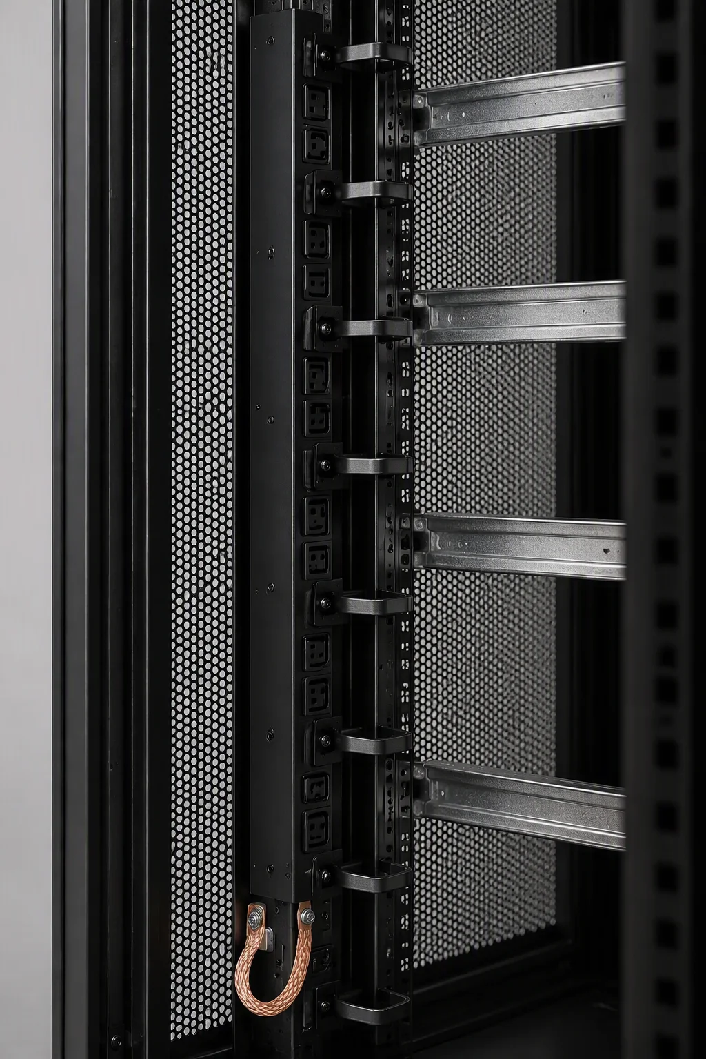
PDU rails, lacing arms and braids, fitted before packing
The rear of a 132 kW cabinet carries more copper than the front carries silicon. Treating it as an engineered surface — rails set, bars pitched, braids bonded — is what separates a row that a technician can service from one he has to excavate.
- PDU rails: 0U rear-post mounts with ±65 mm depth travel and a 30 kg rating per rail, drilled to your PDU model's mounting pattern.
- Lacing arms: bars at a 4U pitch (2U dense option) with rolled edges, so ties hold the bundle without shaving the jacket.
- Trough brackets: welded carriers for 100×100 mm SGCC overhead sections; 200×100 mm high-fill carriers on GPU rows.
- Ground braids: 6 mm² cabinet-to-cabinet fitted at the factory, 16 mm² row-to-grid lugs packed in the same kit — continuity logged at ≤0.1 Ω per cabinet.
Kits for existing frames bolt to standard EIA-310-E punching with the same hardware, so retrofits do not need a second drawing set.
The kit, sheet by sheet
One kit services one cabinet; the row-level bond lugs and trough sections scale with the row. All sheet-steel parts cross the same four-stage pretreatment and powder line as the racks, so kit and cabinet age at the same rate in the same hall.
| Parameter | RF-PWR Specification |
|---|---|
| PDU mounting rails | 2 vertical 0U rails per cabinet, rear-post mounted |
| PDU rail load rating | 30 kg per rail · holes drilled to PDU model pattern |
| Rail depth adjustment | ±65 mm travel, U-marked |
| Lacing bar pitch | 4U standard · 2U dense option on GPU rows |
| Cable trough sections | 100×100 mm standard · 200×100 mm high-fill, SGCC 1.5 mm |
| Bend radius reserved | power 6× OD · copper 4× OD · fiber 10× OD, minimum |
| Grounding braid, cabinet-to-cabinet | 6 mm² tinned copper, factory-fitted |
| Grounding bond, row-to-grid | 16 mm² tinned copper lugs, supplied in kit |
| Ground continuity | ≤0.1 Ω per cabinet, tested and logged at outgoing |
| Bracket and bar material | SPCC 1.5–2.0 mm, deburred and edge-rolled |
| Finish | degrease → pickle → phosphate → powder coat, 80–100 µm |
| Colors | RAL9004 / RAL9005 / RAL7035 · braids green-yellow |
| Kit net weight | 8–12 kg per cabinet depending on trough option |
| Trade terms | MOQ 5 kits · sample 15 days · production 30 days · FOB Qingdao |
Keep the rear panel as engineered as the front
30 kg rails · 4U lacing pitch · ≤0.1 Ω logged per cabinet