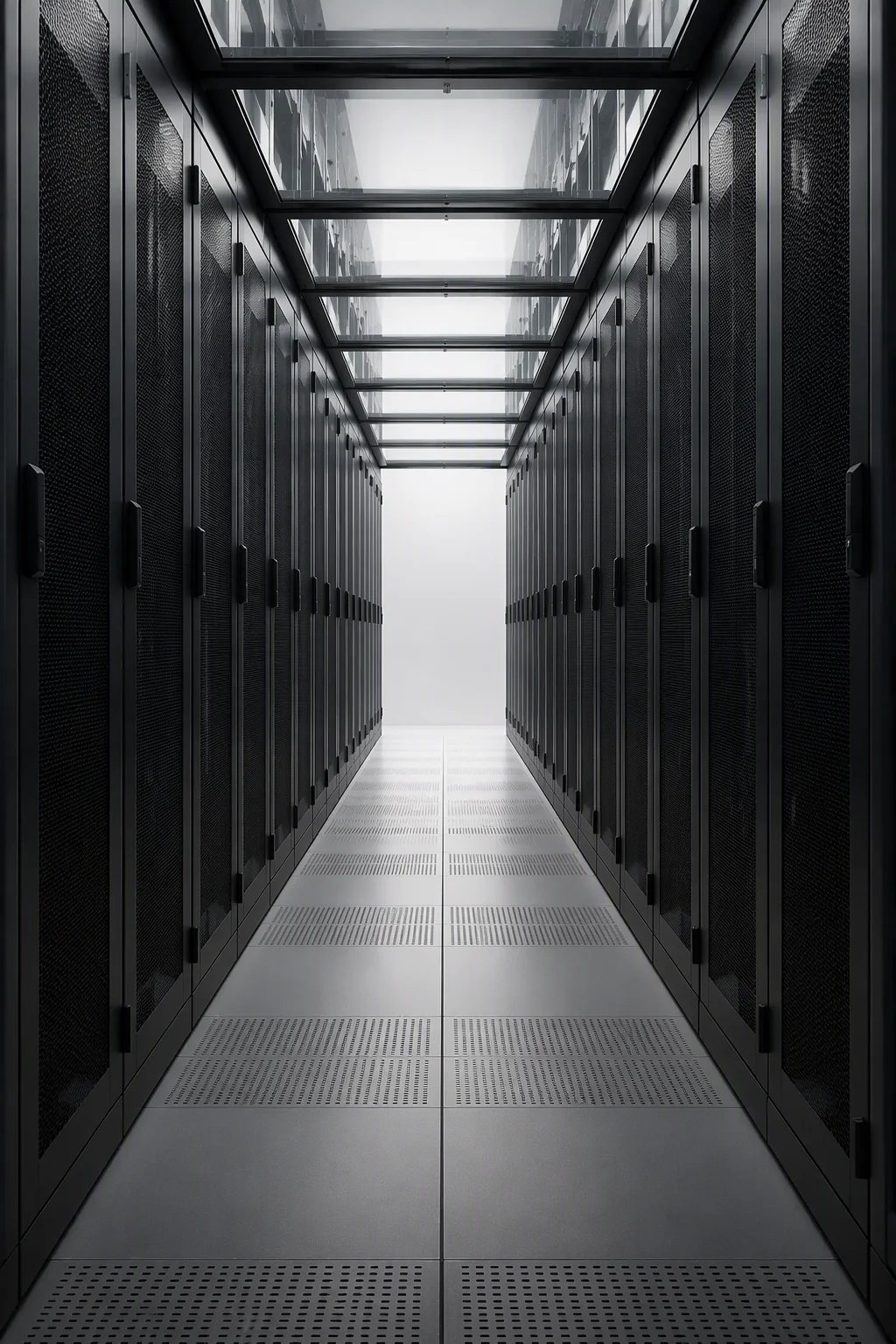
Busway-Integrated Rack Columns, Tap-Off Stations from 250 A to 800 A
A rack column can be a passive post, or it can be the tap-off station of the row. Ours arrive the second way: both verticals slotted with a continuous track channel, tap-off box brackets drilled to the track maker's hanger pitch, SGCC cable troughs pre-hung from tap-off to cabinet top, and grounding jumpers fitted with continuity logged at ≤0.1 Ω. Top feed and under-floor feed are both pre-drilled, so that choice can wait until the single-line drawing closes. The family is cut to four track classes — 250, 400, 630 and 800 A — and engineered to the benchmark class set by Vertiv SmartRun's suspended power spine, where up to 400 kW per rack position and 4,000–8,000 A routing define the high-density ceiling. Those are design-alignment figures; the records we ship are structural: continuity, load and track alignment on our own jigs.
Request a Quotation Jump to Specifications
4 track classes · ≤320 A tap position · ≤0.1 Ω ground
Four classes, one column geometry
Class choice follows the row, not the catalogue. Industry practice has already shifted: rows planned at 400 A a decade ago are spec'd at 800–1,600 A where AI density lands. All four classes below share the same column, bracket and trough geometry, so a row can start at BUS-400 and step up to BUS-800 without changing the structure underneath it.
Edge rows and network blocks
One 125–160 A tap-off feeds a mixed 5–10 kW row; under-floor feed keeps the ceiling line clean for containment roofs.
General compute rows
The classic 400 A class, now usually paired as twin 160 A tap-offs so A and B feeds land on opposite columns of each cabinet.
GPU air-cooled rows
Twin 250 A tap-offs carry rows running close to the 40 kW airflow ceiling, with trough depth reserved for the fatter power cords.
NVL72-class liquid rows
Dual 320 A positions mirror the 4-bus benchmark geometry that delivers up to 400 kW per rack position in design alignment.
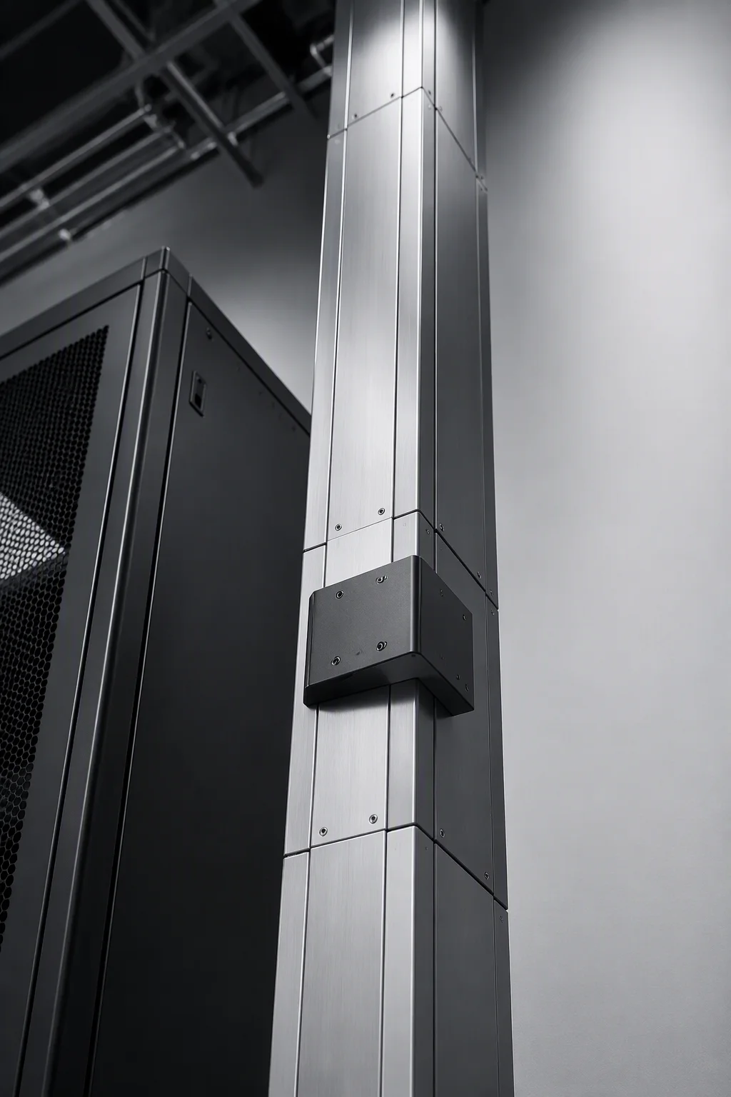
Top feed or under-floor — the brackets arrive welded on
Neither feed path should be invented on site. Both are cut, drilled and marked at the factory against the project's single-line drawing, so the electrician lands cables instead of drilling steel two metres above a live aisle.
- Top feed: the track hangs above the row on hangers at the supplier's pitch; our alignment jig drills both columns of a bay in one setting, so tap boxes sit square to the aisle.
- Under-floor feed: riser notches and floor-box alignment marks are cut at the factory — no field drilling near the feed path, and the ceiling stays free for containment roofs.
- Tap-off brackets: up to two boxes per rack position at ≤320 A each in the 800 A class — the geometry the 400 kW-per-position benchmark assumes.
- Cable troughs: SGCC 1.5 mm sections with deburred edges, sized so a 320 A tap cable lands on the cabinet top with its 6× OD bend radius intact.
Every column leaves with its silk-screened ID zone mapped to the drawing revision in the shipping file, so site crews match brackets to drawings without opening a single loose-parts box.
The structural sheet for the tap-off station
Scope discipline keeps this sheet honest: RackForge supplies the structure — columns, brackets, troughs, junction boxes and grounding — while the electrical ratings of the installed track are certified by the track supplier. Rows marked "design class" are our engineering alignment targets, not substitute certificates.
| Parameter | RF-BUS Specification |
|---|---|
| Rated current classes | 250 / 400 / 630 / 800 A (BUS-250 to BUS-800) |
| Tap-off capacity per rack position | up to 2 plug-in boxes, ≤320 A each — design benchmark class |
| Short-time withstand, track design class | 20–50 kA / 1 s graded by track class, documented per project |
| Protection rating | IP2X standard · IP54 optional on enclosed runs |
| Ground continuity | ≤0.1 Ω column-to-column, jumpers factory-fitted and logged |
| Track conductor, design class | aluminium, graded per class — e.g. BUS-400 at 80×8 mm per phase |
| Temperature rise, design target | ≤70 K at rated current on accessible surfaces, IEC 61439 alignment |
| Column material | SPCC 2.0 mm, five-bend formed, five-fold stiffness path |
| Trough material | SGCC 1.5 mm, deburred edges, 100×100 mm standard section |
| Hanger pitch | drilled to your track maker's drawing · standard jig 500 mm |
| Feed arrangements | top feed or under-floor feed, both pre-drilled at the factory |
| Standards alignment | IEC 61439-2 / UL 857 as track-side references · rack frame EIA-310-E |
| Finish | degrease → pickle → phosphate → powder coat, 80–100 µm, C4 class |
| Trade terms | MOQ 5 column sets · sample 15 days · production 30 days · FOB Qingdao |
Benchmark note: the 400 kW/position ceiling and 4,000–8,000 A routing class reference published suspended-system figures; RackForge test records cover structure, brackets, troughs and grounding.
Set the spine before the row stands
250–800 A track classes · 2 × 320 A positions · ≤0.1 Ω ground, logged