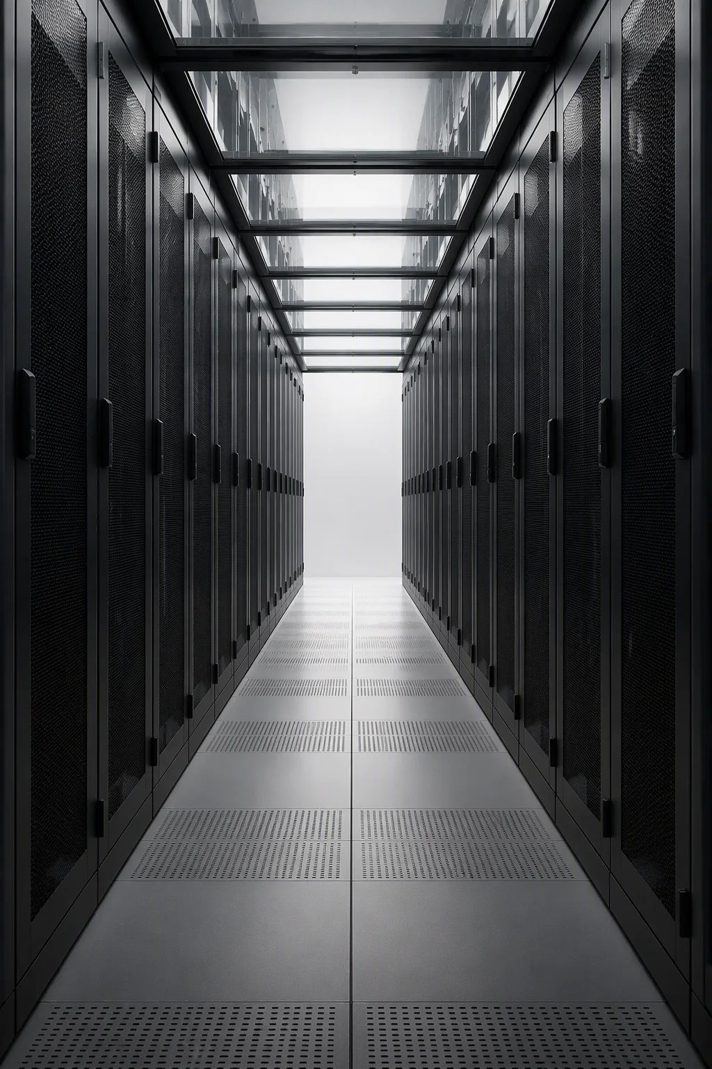
Integrated Rack Structures — Busway Columns, Power Hardware and OEM Sheet Metal from One Line
Structures that carry the power path, so the racks only carry compute. Busway-integrated columns arrive as tap-off stations with brackets and cable troughs welded in place. PDU rails, lacing bars and grounding braids are fitted before the crate closes. The same floor takes contract sheet metal from 0.8 to 3.0 mm at a ±0.1 mm fabrication tolerance. The family is engineered to the benchmark class set by suspended pre-integrated power systems such as Vertiv SmartRun — a 400 kW per rack-position design ceiling, 4,000–8,000 A routing classes and the roughly 85% deployment-speed gain that class reports over field-built runs. Those are design-alignment figures; the records we ship are structural: ground continuity ≤0.1 Ω, static load and track alignment, tested on our own jigs.
Request a Quotation Compare the Three Lines
Three lines · 400 kW/position design ceiling · ≤0.1 Ω ground continuity
Three lines, one row, one drawing set
Each line answers a different part of the aisle. The busway line feeds it: columns slotted for 250–800 A track classes with tap-off brackets drilled at the pitch your track supplier specifies. The power line services it: PDU rails, lacing bars and trough brackets that keep a 132 kW cabinet's rear panel navigable for the life of the hall. The OEM line builds everything else: contract parts in SPCC, SGCC, SUS304 and AL5052 on the same six processes, with CMM first articles and batch traceability. Field busbar work on a conventional row adds 2–3 weeks of site time per hall; structures that arrive pre-integrated aim the schedule at crane-to-live-load inside the same week.
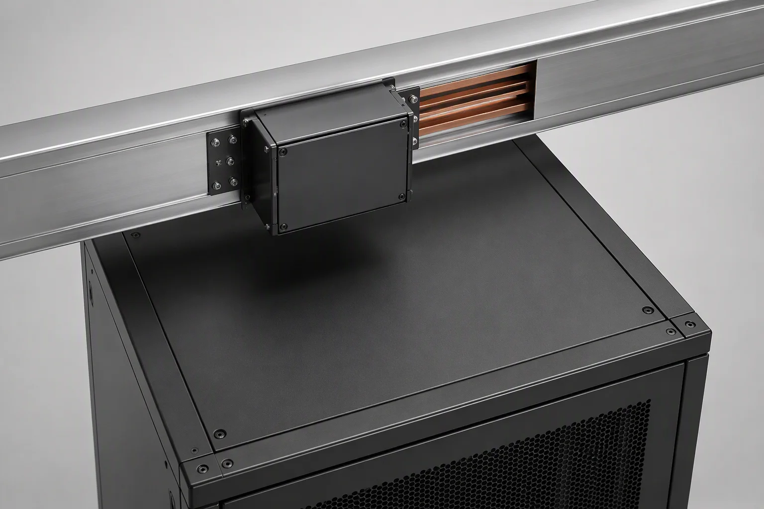
Busway-Integrated
Columns engineered as tap-off stations: continuous track channels, tap-off box brackets to the track maker's pitch, SGCC troughs pre-hung, top feed or under-floor feed pre-drilled. Ground continuity ≤0.1 Ω logged per cabinet.
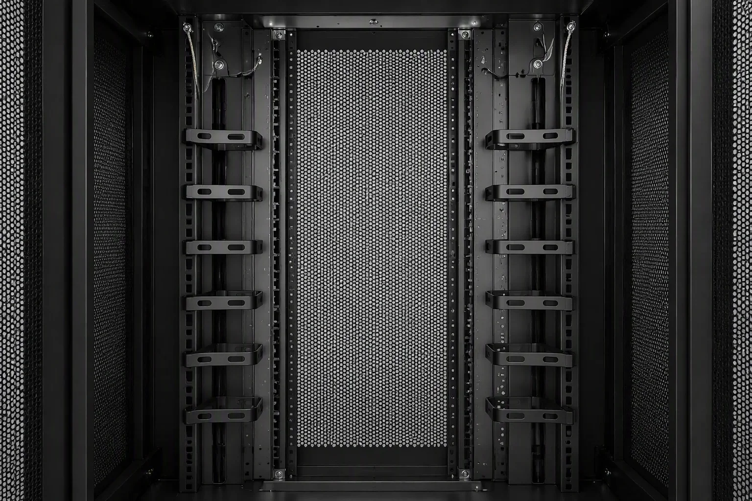
Power & Cable Structures
Vertical 0U PDU rails rated 30 kg, lacing bars on a 4U pitch with 2U dense option, overhead trough brackets for 100×100 mm sections, and 6 mm² grounding braids fitted at the factory — hardware that keeps a 132 kW cabinet serviceable.
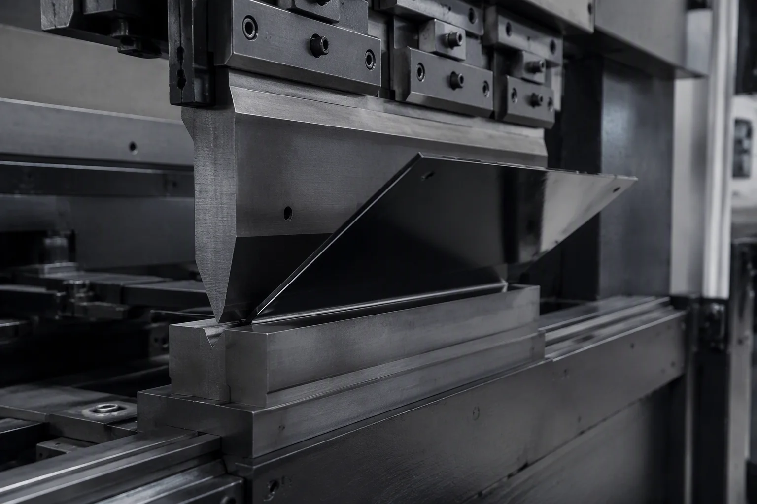
Sheet Metal OEM
Contract parts under drawing NDA: SPCC, SGCC, SUS304 and AL5052 from 0.8 to 3.0 mm at ±0.1 mm, four-stage pretreat, C4-class powder at 80–100 µm, 480-hour salt-spray validation and CMM first-article reports.
Six items arrive on the structure, not in a loose-parts box
Pre-integration only counts if the mounting hardware leaves inside the structure. Every item below is fitted at the factory and inspected at outgoing, and the part-marking zone ties each bracket, trough and box to the drawing revision it was built to — so the site crew assembles nothing and guesses nothing above a live aisle.
Busbar slot columns — both verticals carry a continuous machined track channel, aligned for top feed or under-floor feed per the single-line drawing.
250–800 A classesTap-off box brackets — positions drilled to the track maker's hanger pitch with finger-safe clearances kept; up to two boxes per rack position in the 800 A class.
≤320 A / positionDistribution boxes — sheet-steel junction boxes with feeder and tap knockouts, surface-mounted where the single-line drawing calls them; IP54 enclosure on request.
IP54 optionPDU mounting rails — two vertical 0U rails per cabinet, rear-post mounted with ±65 mm depth travel, rated 30 kg per rail.
30 kg / railGrounding jumpers — tinned-copper braids fitted frame to frame before packing, with column-to-column continuity tested and logged at outgoing.
≤0.1 Ω continuityFactory part marking — a silk-screened identification zone on every structural member; brackets, troughs and boxes carry the zone ID of the drawing revision they were made to.
ID zone · silk-screenOne spec sheet across the three lines
Naming carries across the family: RF-BUS-800 is an 800 A-class column set, RF-PWR-KIT is the power hardware kit, and OEM parts carry your part number with an RF run batch. Where a figure below is a benchmark class rather than a RackForge test record — the 400 kW position ceiling, the tap-box amperages — it is marked as design alignment; the track supplier's certification file completes the electrical picture.
| Parameter | Busway-Integrated | Power & Cable | Sheet Metal OEM |
|---|---|---|---|
| Core product | tap-off ready columns, troughs, junction boxes | PDU rails, lacing bars, ground kits | contract parts and sub-assemblies |
| Current / load class | 250–800 A track classes · 400 kW/position design ceiling | 30 kg per PDU rail · 132 kW cabinet envelope | part loads per customer drawing |
| Protection rating | IP2X standard · IP54 optional on enclosed runs | IP20 structures | per drawing · IP54 builds available |
| Material | columns SPCC 2.0 mm · troughs SGCC 1.5 mm | SPCC 1.5–2.0 mm brackets and bars | SPCC · SGCC · SUS304 · AL5052 |
| Thickness range | 1.5–3.0 mm structural members | 1.2–2.0 mm | 0.8–3.0 mm |
| Fabrication tolerance | ±0.1 mm | ±0.1 mm | ±0.1 mm, laser through assembly |
| Ground continuity | ≤0.1 Ω column-to-column, jumpers fitted | ≤0.1 Ω with bonded braids, logged | bonding points on request |
| Finish | 80–100 µm powder, C4 class | 80–100 µm powder, deburred edges | powder or wet paint per drawing |
| Factory testing | ground continuity · track alignment on jigs | rail load checks · continuity log | CMM first article · 480 h salt-spray class |
| Documentation | layout sheet + alignment record | cable plan + grounding schematic | DFM notes + CMM report |
| Lead time | 30 days · 15 days sample | 30 days · 15 days sample | 30 days · 15 days sample |
| MOQ | 5 column sets | 5 kits | 5 per part number · 1-piece prototypes |
Trade terms are common to all three lines: FOB Qingdao · CIF/DDP on request · T/T or L/C · 3-year warranty on structure and coating.
Three questions buyers ask first
No — and we label them so. They are the design benchmark values published for the suspended pre-integrated class (Vertiv SmartRun's figures) that our slot pitches, bracket ratings and trough loading are engineered to meet. RackForge's own records cover the structure: ground continuity ≤0.1 Ω per cabinet, static load on columns and track alignment on jigs. The electrical certification of the installed track comes from your track supplier under IEC 61439-2 or UL 857, and we file it with the project documentation.
Yes. Send the track maker's hanger pitch and tap-box mounting drawing with your enquiry; the DFM reply lands within 48 hours. Holes are drilled at your supplier's pitch in our alignment jig, so both columns of a bay stay square to the aisle, and tap positions accept up to two boxes per rack position in the 800 A class. Junction box locations follow your single-line drawing, and the silk-screened ID zones are mapped to that revision in the shipping file.
Minimum order is 5 per SKU or part number, with 1-piece prototype runs accepted on OEM work. Samples ship in 15 days and production in 30 days after drawing sign-off, priced FOB Qingdao with CIF and DDP available; payment is by T/T or L/C. Structure and coating carry a 3-year warranty, and every order leaves with its test records and the dual-unit drawing package in the crate — export plywood crates, or CKD flat-pack when container volume matters.
Put the power path in before the racks land
250–800 A track classes · 400 kW/position design ceiling · ±0.1 mm OEM sheet metal