Liquid-Cooling Ready Racks with Manifolds and UQD Pre-Installed
Direct-to-chip loops fail in the last metre, so we build that metre in the factory. Coolant manifolds run above both front and rear doors, UQD quick-disconnect pairs land at fixed positions, drip pans sit under every union, and the whole loop is pressure-held at 1.5× working pressure for 24 hours before dispatch — the zero-drop record ships inside the crate. Design flow is 25–80 L/min per rack on PG25, covering the 40–132 kW liquid envelope of the family. In-rack CDU and in-row CDU docking geometries follow published OCP-aligned practice, so the rack meets the plant your facility team already runs.
Request a Quotation Jump to Specifications
1.5× / 24 h pressure hold · 25–80 L/min · PG25
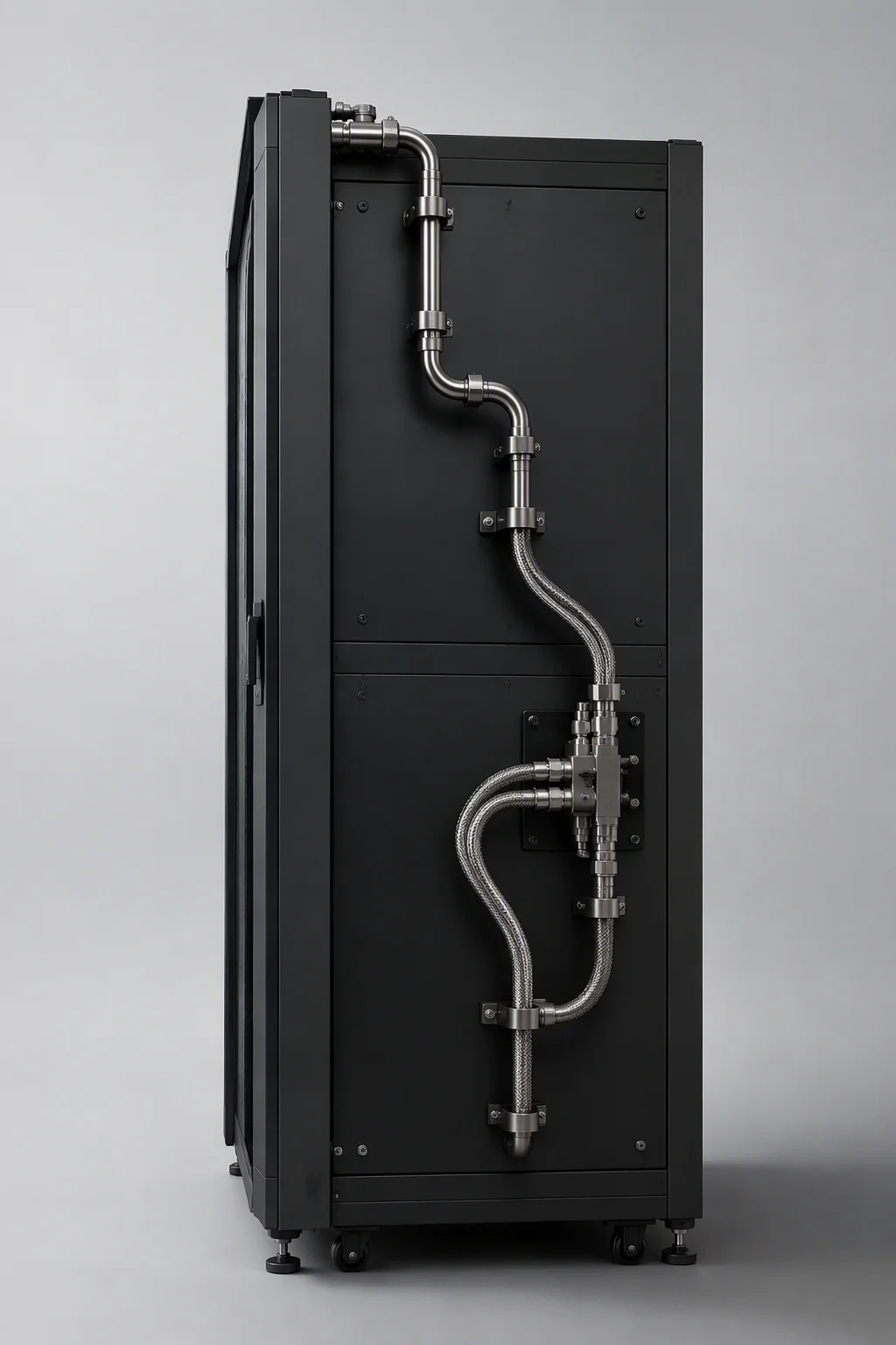
Piped, pressure-held and documented before it is crated
Manifolds route above the front and rear doors, keeping every U of rack space for compute instead of plumbing. Branch positions are drilled to the approved layout drawing, and each assembly is numbered against the drawing revision it was built to, so site crews always know which revision is inside which crate. Nothing on the wet loop is left as field work.
- Above-door routing: supply and return headers run over both door lines, so floor space, side panels and cable paths stay untouched.
- UQD positions: quick-disconnect pairs sit at fixed, repeatable coordinates for CDU-side hookup — drip-less bodies, capped and tagged at dispatch.
- Drip management: pans under every union and filler catch service drips; a leak-sensing rope per rack is the one option to tick.
- Factory proof: the loop is held at 1.5× working pressure for 24 hours; the pressure-drop record travels with the goods, serial-matched to the rack.
Hydraulic sheet, benchmarked to shipped CDU classes
CDU and heat-capture figures below are design alignment targets drawn from published DLC-2-class system data — we quote them so your facility team can match the rack to the plant it will meet, not as capacity claims of our own.
| Parameter | RF-LC Specification |
|---|---|
| Design flow | 25–80 L/min per rack, balanced per branch |
| Working fluid | PG25 — 25% propylene glycol / water |
| Quick disconnects | UQD pairs, OCP-aligned interface, drip-less, capped and tagged |
| Manifold routing | above front and rear doors, drilled to approved drawing |
| Branch bore | DN50 (2 in) rack manifolds · DN100–DN150 row headers, design alignment |
| CDU interface, design benchmark | in-rack CDU ≤250 kW class · in-row CDU ≤1.8 MW class |
| Heat-capture benchmark | DLC-2-class direct-to-chip loops capture ~98% of IT heat |
| Warm-water operation, design benchmark | 45°C facility water — chiller-free envelope |
| Power envelope per cabinet | 40–132 kW, NVL72-class liquid builds |
| Pressure test | 1.5× working pressure · 24 h hold · zero-drop record shipped |
| Leak detection | drip pans standard · per-rack leak-sensing rope optional |
| Frame and load | SPCC frame · 1,600 kg static load · 800 × 1200 mm |
| Grounding | manifold-to-frame bonding ≤0.1 Ω |
What is in the crate with a liquid-cooling rack
Six items, all factory-fitted or serial-matched, so the commissioning crew connects headers and starts flowing coolant instead of assembling hardware over a live floor. The two documents that matter — the 24-hour pressure record and the layout drawing revision — travel with the hardware they describe, not in a separate email thread.
Manifold assembly, pre-mounted — supply and return headers routed above both doors, drilled to the signed layout drawing.
front + rearUQD quick-disconnect pairs — drip-less bodies at fixed coordinates for CDU-side hookup.
OCP-alignedFlexible hose whips — cut and crimped to the lengths on the approved plan, labeled per branch.
length per planDrip pans — seated under every union and filler point before the loop is closed.
standard fitPressure-test record — 1.5× working pressure held 24 hours, zero drop, serial-matched to the rack frame.
in crateGrounding jumpers — manifold-to-frame bonding straps fitted, keeping the wet loop inside the continuity limit.
≤0.1 Ω
Connect the headers. The plumbing is already proven.
1.5× / 24 h pressure hold · 25–80 L/min · 40–132 kW envelope