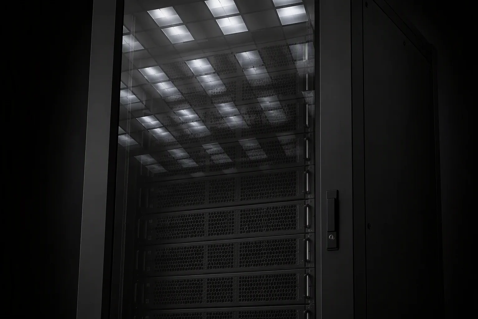
Every AI rack project starts with the same mismatch. The floor was drawn for one power era; the cluster that lands on it belongs to another. Surveys of large facilities still find most cabinets running at 10–30 kW, while the cabinets being quoted for AI deployments start where those leave off. The gap is not incremental — it is an order of magnitude, and it arrives as three separate problems at once: structure, feed and heat.
The power curve moved faster than the installed base
Cabinet power has not drifted upward — it has stepped through distinct eras, each one breaking assumptions the previous one was built on:
- 5–10 kW — the traditional enterprise cabinet: 1–2 servers' worth of distribution, a single 16 A feed, air cooling as an afterthought.
- 40–80 kW — H100-class training builds: denser trays, three-phase feeds, and the first time buyers had to think about rack-level thermal limits.
- 132 kW — GB200/GB300 NVL72-class liquid builds, rated in the 120–140 kW continuous band and commonly quoted at 132 kW, delivered by eight 1U power shelves of 33 kW each.
- 240 kW — next-generation AI cabinets already being requested by colocation operators, with the publicly discussed 2027 rack class heading toward roughly 600 kW per cabinet.
Meanwhile the average cabinet in operation has climbed to about 27 kW — 4.5 times the 6.1 kW baseline the industry grew up with, and up 69% on the ~16 kW measured only a year earlier. The installed base did not move at that speed; that is precisely where the retrofit market comes from.
Why 40 kW is where air hits the wall
Air is a working fluid with a filing limit. Moving 40 kW of heat out of one cabinet with a 10 °C air-side temperature rise demands roughly 12,000 m³/h — about 7,000 CFM — pulled through a single 600 mm-wide frame by the server fans themselves. At 132 kW the same equation asks one cabinet to swallow around 39,600 m³/h, which no practical fan wall, rack mesh or hot aisle can convey without the room becoming the duct.
Rule of thumb: every 4 kW of IT load at a 10 °C rise costs roughly 1,200 m³/h of airflow through the cabinet. The bill scales linearly; the cabinet does not.
Open aisles make the arithmetic worse — in uncontained rooms, 25–50% of conditioned air bypasses the load entirely and short-circuits back to the cooling units. Past roughly 40 kW per cabinet, direct-to-chip liquid stops being an efficiency option and becomes a physical requirement.
What changes inside a liquid-cooled cabinet
A liquid-ready frame is not a standard rack with hoses. The structural differences concentrate in the coolant path: manifolds routed above both door lines so supply and return never cross the service zone, UQD quick disconnects mounted at fixed coordinates so any CDU can dock without re-engineering, and drip pans under every union so a service event is a maintenance line item, not an insurance claim. The design envelope RackForge works to: 25–80 L/min per cabinet on a PG25 water–glycol loop, with the rack side sized to dock CDUs in the in-rack class up to 250 kW. The factory proof matters as much as the geometry — before the crate closes, the assembled loop holds 1.5× working pressure for 24 hours, and the zero-drop record ships inside with the rack.
Load and feed: the two checks that stall projects
Structure first. Many catalog frames still carry static ratings in the 1,000–1,363 kg class, sample-tested at best. A loaded NVL72-class build with manifolds, cabling and power shelves asks for more; RackForge frames are rated 1,600 kg static and verified at a 4× safety factor with a 72-hour creep recheck before release — a number on a test log, not a catalogue line.
Feed second. The industry has moved from planning busbar at 400 A per position to 800–1,600 A classes for AI rows. Rack columns with machined tap-off slots carry feed to a 400 kW per rack-position design ceiling, with plug-in tap-off classes in the 250–800 A band, so capacity follows the row instead of the floor plan. Both checks buy time you will need: utility uprating in major markets takes 12–24 months at over $2M per MW, and each CDU adds $20,000–35,000 — which is exactly why the rack-side interface should be frozen before the cooling plant is ordered.
The six-line sizing checklist
Fix the kW envelope per cabinet first — 40 kW air / 132 kW liquid / 240 kW next-gen — before any chassis is chosen.
132 kW NVL72-classVerify frame static load at 4× — 1,600 kg class with a documented 72-hour hold and creep recheck.
1,600 kg · 4×Plan feed per position, not per hall — busbar-slot columns to a 400 kW/position ceiling, tap-off classes 250–800 A.
≤400 kW / positionFreeze UQD coordinates early — manifold above both door lines, CDU docking side agreed before the CDU order.
25–80 L/min · PG25Check the slab and the route — 1,600 kg static per cabinet, plus door clearances and floor rating along the transport path.
per-cabinet static + routeKeep containment on the same module — 600 mm CAC compatibility so the row seals correctly from day one.
600 mm moduleWhere to go deeper
The rack is the boundary your cluster actually touches, and it is the one component you can fix without waiting for the grid. The two builds this guide refers to are specified in full on the GPU high-density rack page — the 40–132 kW envelope, NVLink bracing and the 4× load record — and the liquid-cooling-ready rack page, where manifolds, UQD pairs and the 1.5×/24 h pressure proof are part of the standard delivery. Bring the kW target; the frame, feed and coolant path can be quoted around it within days.