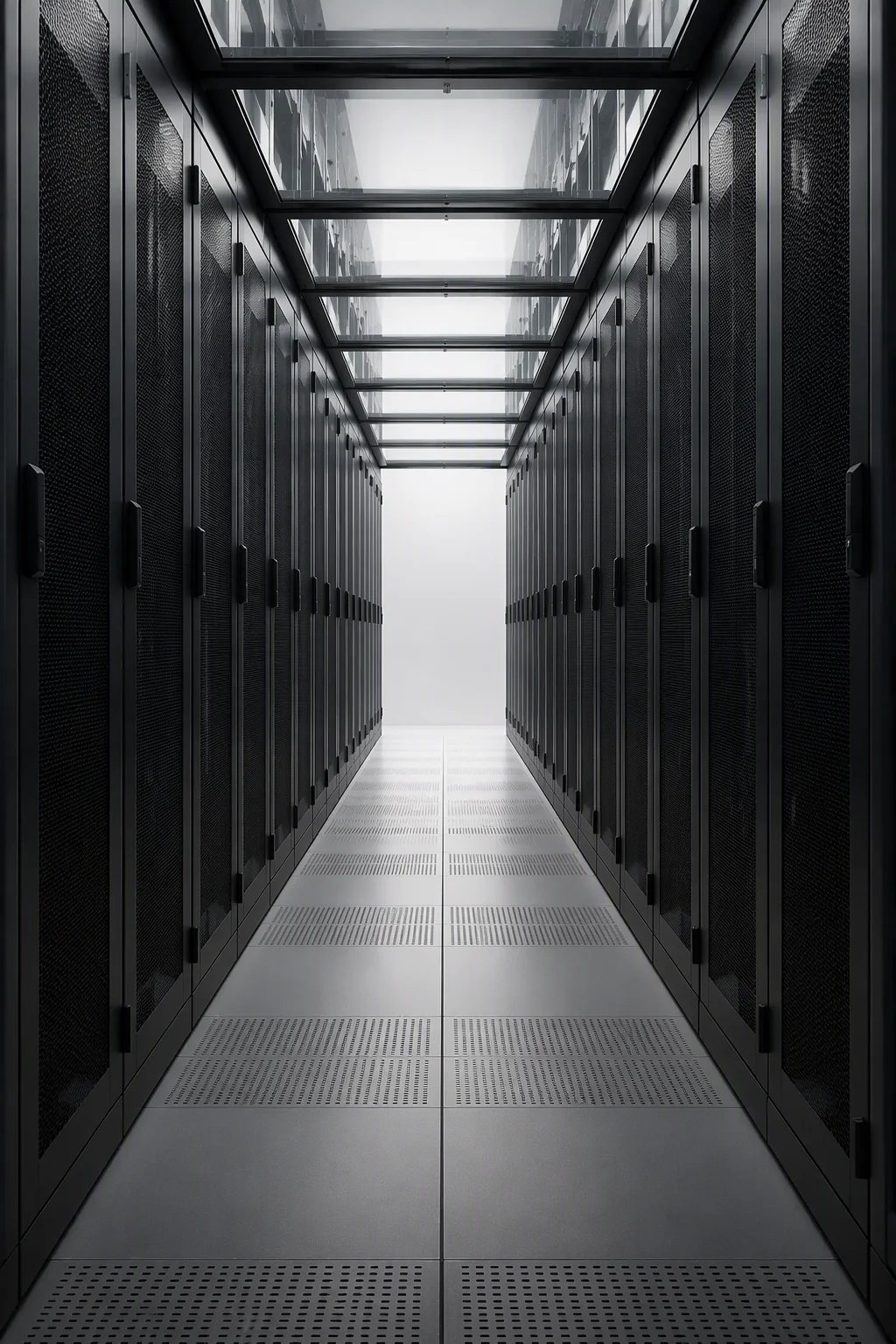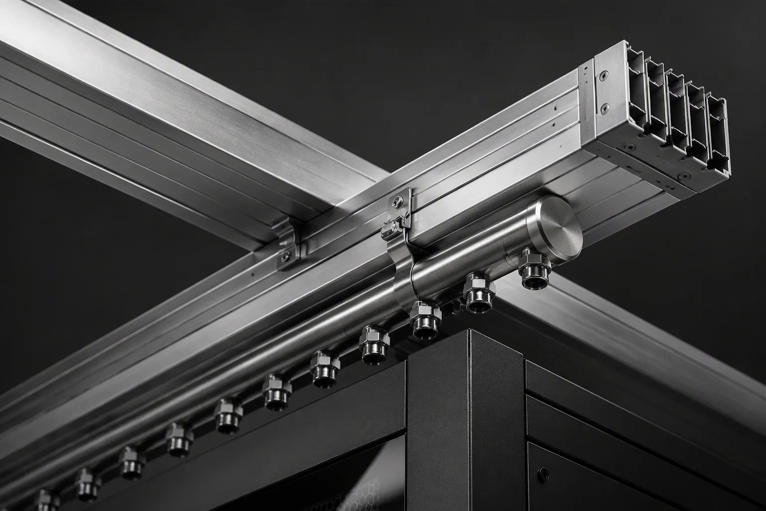
The industry has already re-planned its rows once. Positions specified at 400 A a decade ago are being written at 800–1,600 A where AI density lands, and the 400 kW per rack-position class now defines the high-density ceiling that suspended systems are engineered against. A rack ordered into that environment has two options: be the object the electrician has to modify, or be the station the tap-off box was designed to land on.
The tap-off box is the interface, so design it first
A plug-in tap-off box does three jobs: it grips the track's conductors, it houses the protection and metering for the branch it feeds, and it presents a cable exit to the cabinet. Each job constrains the rack column:
- The grip sets the bracket. Tap-off boxes are hung from brackets drilled to the track maker's hanger pitch. RackForge columns are drilled to that drawing — standard jig at 500 mm — so the box hangs square to the aisle rather than being shimmed level on site.
- The cable exit sets the trough. A 320 A tap cable needs its 6× outside-diameter bend radius respected on the way to the cabinet top. SGCC 1.5 mm troughs with deburred edges in a 100 × 100 mm standard section carry that fill; 200 × 100 mm high-fill sections are specified on GPU rows where the bundle is fatter.
- The protection sets the position count. Independent A and B feeds mean two boxes per rack position, which is why the column is slotted for up to two tap positions rather than one.
Freeze this interface before the track is ordered. The tap-off class, the hanger pitch and the feed arrangement are three numbers that arrive on one drawing, and changing any of them after the columns are punched means field drilling above an aisle.
Ampacity: three different ratings people call "the busbar rating"
Ampacity conversations go wrong because three unrelated numbers get quoted as one. Keep them separate and the sizing arithmetic becomes trivial:
| Rating | What it governs | Typical class on this family | Who certifies it |
|---|---|---|---|
| Track rated current | The continuous current the run itself may carry, and the short-time withstand of the whole spine | 250 / 400 / 630 / 800 A classes; 20–50 kA for 1 s graded by class | Track supplier, to IEC 61439-2 / UL 857 as track-side references |
| Tap-off capacity per rack position | How much current may be drawn at one cabinet without re-engineering the column | Up to 2 plug-in boxes, ≤320 A each | Joint: track supplier for the box, rack drawing for the bracket |
| Design ceiling per position | The planning figure used to size the row for a future load, not a nameplate | ≤400 kW per rack position in design alignment | Engineering target, documented as such |
The useful consequence of separating them is that a row can be procured in stages. All four track classes share the same column, bracket and trough geometry, so a row can start on BUS-400 for general compute and step to BUS-800 for NVL72-class liquid builds without changing the structure underneath it. What cannot be staged is the drilling: the bracket pattern is set when the column is punched.
- BUS-250 — edge and network rows, one 125–160 A tap position, mixed 5–10 kW cabinets.
- BUS-400 — general compute, usually twin 160 A tap-offs so A and B land on opposite columns of each cabinet.
- BUS-630 — air-cooled GPU rows running close to the 40 kW airflow ceiling, twin 250 A tap-offs, deeper troughs.
- BUS-800 — liquid rows, dual 320 A positions mirroring the four-bus benchmark geometry that delivers the 400 kW-per-position figure.
Vertical or overhead: two runs, two different rack problems
Both arrangements are legitimate, and the choice is usually made too late in the project — often after the containment roof is on. The trade is not electrical; it is about service access and what else needs the ceiling.
- Overhead runs keep the floor clear and put the tap-off above the cabinet, which suits rows where the rear panel is dense with cable and coolant. The cost is coordination: the run shares the ceiling with the containment roof panels, LED strips, sprinkler heads and any leak-detection cabling, and the hanger pitch has to respect roof module boundaries.
- Vertical runs place a column-mounted or rack-adjacent busbar with the tap-off at cabinet height, which shortens branch cables and keeps the ceiling free for fire protection and roof panels. The cost is floor and side-panel space, plus a service envelope around the run that must not be blocked by a containment door frame.
- Under-floor feed remains the answer for rooms with an existing raised floor and spare capacity. Riser notches and floor-box alignment marks are cut at the factory, keeping field drilling away from the feed path.
RackForge columns arrive with both top feed and under-floor feed pre-drilled, so the choice can wait until the single-line drawing closes — but only if the rack was ordered with both patterns. Retrofitting the second one is a field operation on a coated column.
Installation sequencing that does not need a return visit
The sequence below assumes the rail is installed before the racks land, which is how field-integrated rows normally fail: frames arrive first, the aisle is built around them, and the electrical crew works over a live floor.
- 1. Single-line closes. Track class, tap-off class, feed route and protection are fixed. This is the last cheap moment to change anything.
- 2. Columns are punched and slotted. Tap-off brackets, hanger patterns, top and under-floor provisions, and the silk-screened ID zone mapped to the drawing revision. ±0.1 mm forming tolerance keeps the pattern true down the row.
- 3. Track hangers go up. The run is levelled against the roof module grid before containment panels are laid in, not after.
- 4. Frames are bayed and anchored. Bayning brackets fitted at assembly; ground continuity measured at ≤0.1 Ω column-to-column with jumpers in place and the reading logged.
- 5. Tap-off boxes engage. One alignment gauge, one try per box, because the bracket was drilled to the track maker's pitch rather than to a field measurement.
- 6. Branch cables land in the troughs. Bend radius intact, bundles dressed, cable ID per the drawing revision in the shipping file.
- 7. Containment closes over the finished row. Roof panels last, so nobody lifts a sealed panel to reach a bracket.
Run in that order, the electrical work happens once, from a clean floor, before the row is live. Run it in any other order and at least one trade returns to a finished aisle.
What to put in the purchase specification
- Tap-off classes and position count — 250/400/630/800 A, up to two positions at ≤320 A each, stated per rack position rather than per row.
- Bracket pitch — quote the track maker's drawing number and the hanger pitch the columns must be drilled to.
- Feed provisions — both top feed and under-floor pre-drilled, with the chosen route marked on the drawing revision.
- Trough section and material — SGCC 1.5 mm, 100 × 100 mm standard or 200 × 100 mm high-fill, deburred.
- Grounding — continuity ≤0.1 Ω with factory-fitted jumpers, logged per cabinet, not measured once per hall.
- Protection class on enclosed runs — IP2X standard, IP54 optional where the run is exposed.
The structural half of this specification is on the busway-integrated racks page: four track classes, both feed arrangements and the tap-off geometry. The cable-side hardware that keeps the rear of a 132 kW cabinet navigable — PDU rails, lacing bars and overhead trough brackets — is on the power and cable management page. For the schedule argument behind factory pre-integration as a whole, see Busbar + Liquid Cooling — The Case for Factory Pre-Integration.