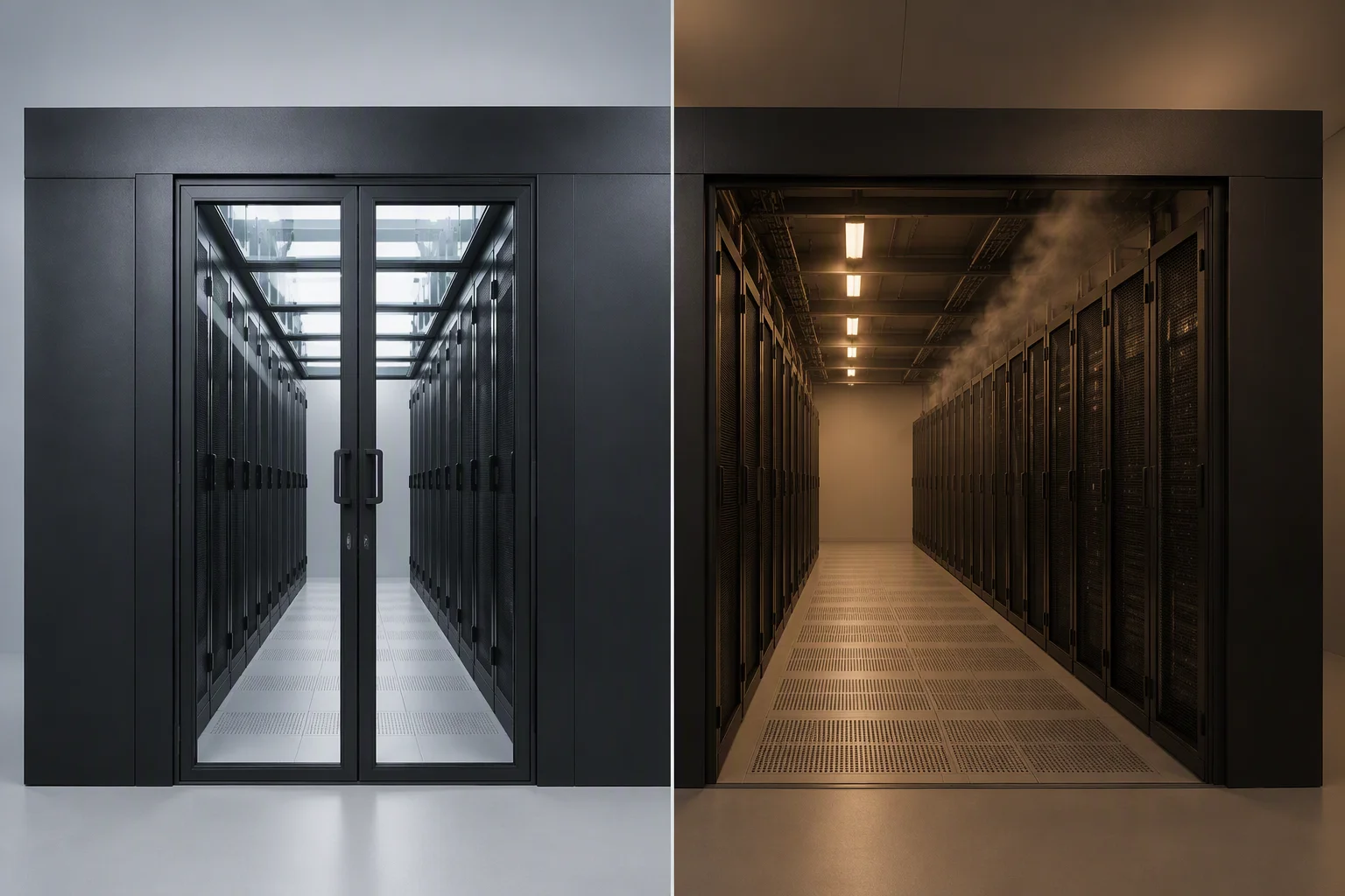
Leakage rate is the single most useful number in a containment specification, and the one most often quoted without its definition. "3–10%" means nothing until you know whether it is a fraction of supply airflow, a fraction of the aisle's air volume per hour, or a pressure-decay figure from a blower-door test. Get that wrong and an aisle can pass its own acceptance test while still short-circuiting a quarter of the cooling plant.
What the percentage is a percentage of
For a contained cold aisle the working definition is a flow ratio: the mass of conditioned supply air that crosses the boundary by a path other than a server inlet, divided by the total supply air delivered to the aisle. That leaked air still costs energy to cool, filter and move, but it never reaches a processor. The band used across this site — 3–10% for a contained aisle, under 1% with a full blanking and brush kit, against 25–50% bypass in an open room — is a flow fraction on that basis. Three related quantities are often mixed into the same conversation and should be kept apart:
| Quantity | What it measures | Typical band | Who owns the fix |
|---|---|---|---|
| Boundary leakage | Supply air escaping through door jambs, panel joints and cable cutouts instead of entering a rack face | 3–10% contained · <1% with full sealing kit | Containment vendor plus the rack's own blanking set |
| Bypass in an open room | Cold air returning to the cooling units without passing through any IT equipment | 25–50% | Nobody — this is the cost of having no boundary |
| Recirculation | Hot exhaust drawn forward into server inlets, usually at the top of a row | Rises with rack power; visible as a vertical inlet-temperature gradient | Blanking panels, brush kits, and where necessary a row fan assist |
Leakage and recirculation pull in opposite directions and are fixed by the same components. Sealing a door jamb stops cold air leaving; filling an open U stops hot air arriving. An aisle that only does the first has closed the room but left the racks porous.
How leakage is actually measured
Four tests appear in the field, and a credible commissioning report says which one was run:
- Flow balance across the cooling units. Total supply airflow is read from the CRAC/CRAH units or from a duct traverse, then compared with the airflow the IT equipment actually draws. The difference, expressed as a percentage of supply, is the leaking fraction. Cheap, quick, and only as accurate as the two measurements feeding it.
- Tracer gas decay. A tracer is released inside the contained aisle and its concentration decay is logged. Air exchange with the surrounding room is calculated from the decay curve. This is the method that gives a true boundary-leakage figure, and it is the one to ask for on a high-density row where the number is contractual.
- Differential pressure with the doors held open. The aisle is pressurized slightly above the room, the doors are opened a measured amount, and the supply fans are observed. The static pressure a containment holds against the room, and how fast it collapses when a leaf opens, are direct indicators of how well the boundary is closed.
- Temperature mapping above the racks. A vertical traverse at the inlet face of the top U shows recirculation. It does not measure leakage, but it is the fastest way to prove that sealing work is needed at all.
Two practical cautions apply to all four. Measure with the row at its design load and with the tiles or grilles in their final position, because an aisle tested empty behaves nothing like a loaded one. And record the doors' state: a leakage figure taken with a leaf propped open for a delivery is not a leakage figure.
Door detailing: where most of the 3–10% lives
Doors are the moving part of the boundary, so they carry the largest single share of the leakage budget. The RackForge door assembly addresses it deliberately rather than cosmetically:
- Brush seal at both jambs, not a single sweep at the leading edge. The frame carries an integral brush so the seal survives leaf movement instead of being dragged along the floor or the roof rail.
- 12 mm tempered glass leaves in an aluminium frame — stiff enough that a double-leaf opening does not bow away from its seal when the aisle runs slightly pressurized, and full-view so a walk-by inspection reads the row without opening anything.
- Release logic that does not leak when idle. Electromagnetic holders release in under 3 seconds on a fire-alarm signal, and the inside handle is push-to-exit. A door designed for emergency egress must still be a closed door on every ordinary day.
- Choose the leaf for the room. A top-hung slider has no swing arc and parks flat against the row; a hinged leaf needs a clear quarter-circle at the aisle end. Both close on the same 600 mm module, so the choice is about room geometry, not about sealing quality.
A door that is left ajar by the last person through is worth less than a cheap door that latches. Soft-close dampers on sliders and magnetic holders on hinged leaves exist for exactly that reason.
Roof panels, cable drops and floor grilles
The roof is the second-largest contributor, and its leakage paths are structural rather than incidental. Panels land on a 600 × 1200 mm module with a brush gasket on the perimeter, seated against rack tops rather than resting on a rail with an air gap above the frames. Cable drops are the compromise: every bundle crossing the roof line is a hole in the boundary, so the cutouts are brush-lined and sized to the bundle rather than to the connector. Floor grilles and under-floor cutouts get the same treatment where power and fiber cross into the aisle.
The drop-away fire panel is the deliberate exception in the whole boundary. Its fusible element holds the flap closed as a sealed panel, releasing below 72°C so the flap rotates 90° clear of the sprinkler envelope, leaving at least 70% of the area below the head open. A sealed ceiling and a sprinkler head want opposite things; the drop-away panel is the mechanical truce, and the fire-alarm linkage test record ships with every order.
Behind the racks, the leakage path belongs to the cabinets. Snap-in steel blanks in 1U–4U and flame-retardant brush kits fit EIA-310-E square-punch openings without tools in under 30 seconds per U, and they are what takes an aisle from the 3–10% band toward the sub-1% figure. Skipping them leaves the most reachable leakage on the floor untouched.
What leakage costs on the meter
The arithmetic between a leakage rate and a PUE number is short. In a widely cited industry measurement, sealing the cold aisle took an uncontained hall from PUE 1.84 to 1.65 in a mild climate — with roughly 37% chiller energy saved either way — and open rooms routinely lose 25–50% of cold air before it reaches a rack face. ENERGY STAR figures attribute up to 10% total-energy and up to 25% IT-fan-energy savings to cold-aisle isolation alone. Once the boundary is closed, the leakage band sets how much of that gain survives:
- Every 1% of leakage is 1% of supply airflow that was cooled, filtered and moved for nothing. On a row drawing serious air volume, that is a continuous fan and chiller load with no compute behind it.
- The residual band is also a mixing path for hot air. Leakage out of the cold aisle at the top of a row is frequently recirculation back in at the same height, which shows up as a hotter inlet at the U where the GPUs are.
- Fan energy follows the boundary, not the leak. A leaky aisle runs at a lower static pressure, so the cooling units push more air to hold the same inlet temperature — a second-order cost that disappears once the seals are fitted.
- Sealing retrofits pay back inside months. The components are panels and brushes; the payback on a full kit is typically measured in a single cooling season, before any chiller capacity is deferred.
Treat leakage as a maintainable asset rather than a build-time number. Doors get opened, tiles get lifted, a contractor pulls a bundle through a roof panel and leaves the cutout unsealed. A walk of the row with a thermal camera once a quarter, and a box of 1U blanks on the shelf, keeps the aisle inside the band it was commissioned to.
The specification language that avoids arguments
- State the definition: leakage as a percentage of supply airflow, measured by tracer decay or flow balance, at design IT load.
- State the target: 3–10% for the containment boundary, under 1% with the blanking and brush kit installed, and name the open-area figure you are replacing.
- Require the panel grid: doors, roof panels and rack tops all on the 600 mm module so a mixed aisle seals as one product rather than three.
- Require the fire documentation: FA linkage test record per order, drop-away release below 72°C, ≥70% clear below the sprinkler when released.
The components in this note are specified across the containment doors page, the roof and fire panel page and the blanking and sealing page, all on the same 600 mm module as the 42U–52U racks they close. If the wider question is which boundary to build first, the companion note Cold Aisle vs Hot Aisle Containment works through that decision order.