Tolerance on a rack drawing is not a quality gesture; it is a fit guarantee. Two frames that differ by 2 mm on their mounting-hole spacing will still accept a server on their own. Bay them into a row of twenty, add containment roof panels drilled to a 600 mm grid, and the error has to go somewhere: a shimmed rail, an enlarged hole, a door that needs a shoulder against it. The ±0.1 mm fabrication tolerance exists so that the error never reaches the aisle.
What capability the line actually has
Tolerance has to be split by process, because each one contributes differently to the final part:
| Process | Capability | What it decides on a rack |
|---|---|---|
| Laser cutting | ±0.05 mm positioning repeatability | Cutout positions, cable entries, manifold pass-throughs and the reference edges everything downstream is measured from |
| CNC punching | ±0.05 mm laser-cut holes · ±0.1 mm punched holes | EIA-310-E square-hole patterns, cage-nut engagement and rail hole alignment down the row |
| Bending | Five-bend forming in one setup, held within the ±0.1 mm envelope | Column straightness, flange angles, and whether a door or roof panel closes on the frame it was drawn for |
| Welding and assembly | TIG, MIG and spot; jigged sub-assemblies | Distortion control — heat input is the largest single source of post-forming movement |
The window the line quotes across all of it is 0.8–3.0 mm sheet in SPCC, SGCC, SUS304 and AL5052, with rack structures built at 1.2–2.0 mm. Frames and load-bearing members use SPCC 1.5–2.0 mm; doors and panels use 1.2–1.5 mm. Nothing about the tolerance changes with gauge — what changes is how much attention the process needs to hold it.
SPCC and SGCC do not form the same way
The two steels that carry most rack structures look interchangeable on a drawing and behave differently at the press brake.
- SPCC (cold-rolled commercial steel) is uncoated, uniform and predictable. Springback is modest and consistent between coils, the bend allowance calculation is stable, and the surface takes pretreatment directly. Its weakness is corrosion: with no zinc, every scratch and cut edge depends entirely on the coating system for protection, which is why the four-stage pretreatment and 80–100 µm film matter more on SPCC parts than on galvanised ones.
- SGCC (hot-dip galvanised steel) brings its own sacrificial protection but a stiffer, less forgiving surface. The zinc layer is softer than the base steel and can flake or micro-crack along a tight bend, and the same nominal thickness forms with noticeably different springback, so a bend program proven on SPCC needs re-proving on SGCC. Welding galvanised sheet releases zinc fume, which means extraction and a dedicated welding procedure rather than a line change.
- Coating over galvanised steel needs its own pretreatment path. Zinc reacts differently in the phosphate stage, so adhesion has to be validated per substrate rather than assumed from an SPCC result. The acceptance test is the same: ISO 2409 cross-cut at class 0.
- Minimum inner bend radius differs by material and is where most crack failures start: 1.0 t for SPCC and SGCC, 1.5 t for SUS304, 2.0 t for AL5052. A design that asks for a radius below the material's limit will form a part that looks acceptable and cracks at the outside of the bend six months later.
On this line the practical division of labour is straightforward: SPCC 1.5–2.0 mm for the structural members that carry the 1,600 kg static rating, SGCC for troughs, cable management sections and parts that live behind a panel in a damp path, and SUS304 or AL5052 quoted when the drawing or the environment calls for them.
Tooling wear: the drift nobody sees on the drawing
A tolerance declared at the start of a production run is held by tooling that is wearing out during it. Three wear mechanisms dominate rack work.
- Punch and die clearance. Cutting clearance is set as a percentage of material thickness, and it grows as the punch wears and the die is reground. Too little clearance accelerates edge wear and can pull the material; too much produces a rolled edge and a burr that grows through the run. Since the hole size is set by the punch and the clearance by the die, a worn punch set drifts the EIA hole pattern long before it fails outright.
- Burr height. A burr is not only a handling hazard; it is a dimensional error on the mating face and a coating defect at the same time. Deburring is scheduled as part of the process rather than as a repair, and it is the reason the trough sections are specified deburred in the rack drawing.
- Bend tooling and backgauges. Punch tips take a set, die shoulders polish, and backgauge references shift by fractions after a heavy run. Five-bend columns formed in one setup are the mitigation: fewer setups mean fewer chances for a reference to move between operations on the same part.
The controls that keep wear inside the envelope are unglamorous: tonnage and stroke counted per tool, regrind intervals set by hole count rather than by calendar, and staged dies kept for the parts that set the row's geometry. Laser positioning repeatability at ±0.05 mm provides the reference that tells the tool room when a punch set has drifted.
First-article inspection: proving the process, then watching it
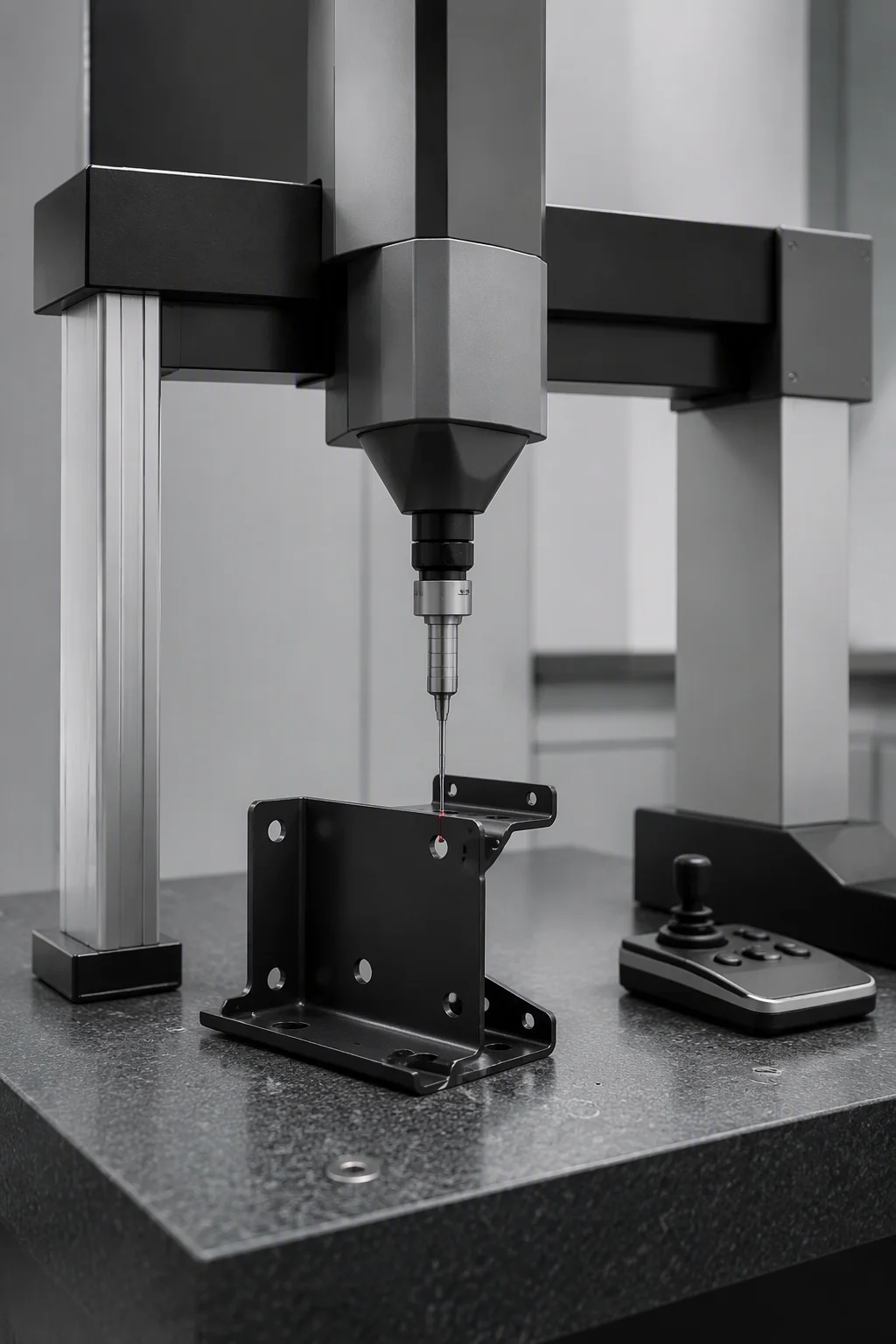
A first article is not a sample of the product; it is evidence that the process is capable of the drawing. RackForge runs it on a CMM against a ballooned drawing — every dimensioned feature numbered, measured and reported individually — before a run is released, and the same discipline applies to contract parts built under drawing NDA.
- Ballooned drawing: every critical dimension carries an ID, and the report returns the measured value against the nominal and the tolerance for each one. A report that lists only pass or fail is not a first article.
- Datum discipline: measurements are taken from the same datums the drawing names. Checking hole positions from a cut edge instead of the datum edge is how a part passes inspection and still fails to bay.
- Material traceability: coil certificates and run batch IDs are retained, and silk-screened ID zones tie a finished part back to its batch and to the drawing revision it was built to.
- In-process checks: the first article proves capability once; batch checks — hole position, bend angle, straightness — keep the run inside the same envelope after the tooling has cut ten thousand holes.
Coating and load records close the loop. Each frame's outbound log carries the proof load result, the creep recheck, the coating adhesion class and the ground-continuity reading on the same serial number, so a dimensional question, a finish question and a structural question all resolve against one document set.
How to specify tolerance so it means something
- Split the tolerance by feature, not by part. Rail hole spacing, cutout position, overall height and diagonal squareness deserve individual limits; a single blanket note hides which one matters.
- Name the material and the gauge on the drawing. SPCC 2.0 mm and SGCC 2.0 mm are different manufacturing instructions and different prices.
- Respect the minimum bend radius — 1.0 t for SPCC/SGCC, 1.5 t for SUS304, 2.0 t for AL5052 — and mark crack-critical bends.
- Require the CMM report with the ballooned drawing, plus material certificates and coating batch records, before the production run is released.
- Ask for the DFM review first. On contract work the review comes back within 48 hours under NDA, and it is cheaper than discovering a forming limit after the dies are cut.
Where that tolerance is bought as a service rather than as rack frames, the capability window — materials, thickness range, hole accuracy, bend radii, coating class, first-article format and trade terms — is published on the sheet metal OEM page. The processes that produce it are walked in order on the factory page, with the inspection station at the end.